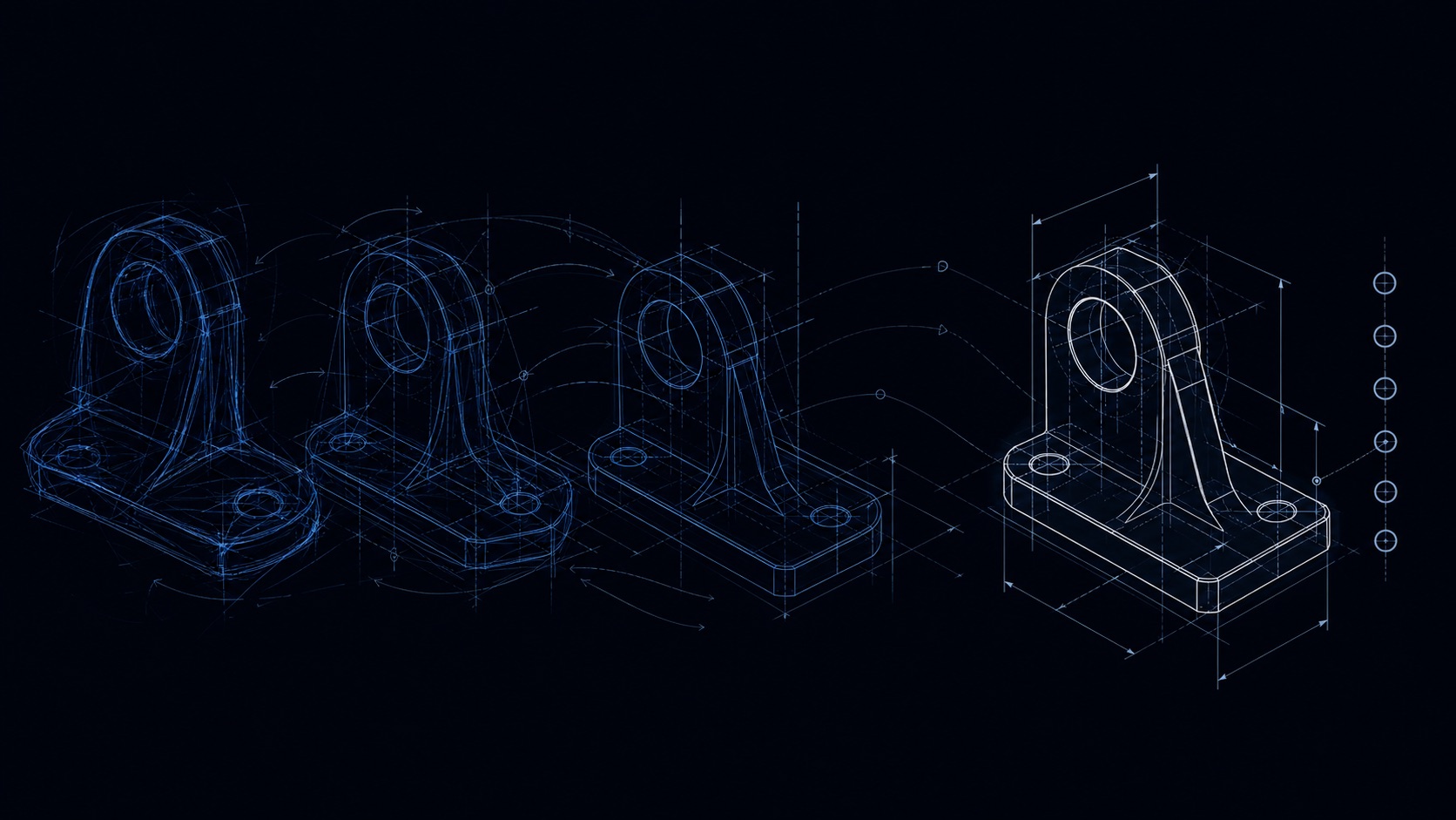
What Actually Transfers When You Move CAD Between Systems
STEP, IGES, and mesh formats carry geometry, not design intent. How to decide which parts to rebuild, which to reuse, and how to plan for drawings.

Moving a design between CAD systems almost always works at the geometry level and almost always fails at the intent level. Understanding exactly where that line falls saves a lot of rework, and it changes how you plan a migration.
Geometry transfer is not design transfer
A neutral exchange format such as STEP (ISO 10303) carries the boundary representation of your model: faces, edges, vertices, and the topology that joins them. Open that file in another system and the shape is there, dimensionally correct, ready for downstream work.
What does not come across is how the shape was built. The sketch that drove the base extrude, the constraint that kept two holes concentric, the feature order, the equations linking wall thickness to a global parameter — none of that survives the round trip. The receiving system sees a finished solid, not a recipe.
This is why an imported STEP body is often called "dumb solid" geometry. The term is unkind but accurate: you can measure it, section it, and build on it, but you cannot go back and change the driving dimension, because there is no longer a driving dimension.
It helps to be precise about what a feature tree actually holds, because that is the list of things you are giving up:
- Sketches and their constraints. Not just the profile curves, but the relationships that hold them together — coincident, tangent, symmetric, equal.
- Feature order. A fillet applied before a shell produces different geometry than the same fillet applied after. The order is part of the design.
- Parameters and equations. A model where
bore_diameterdrives four features at once collapses into four unrelated faces. - Design intent for reference geometry. Datum planes and axes that were meaningful anchors become nothing, or become arbitrary construction leftovers.
Once the tree is gone, the geometry is still perfectly usable. It just stops being a design and becomes a result.
Where each format sits
- Native formats carry the full feature tree, parameters, and constraints, but only within their own system and usually only within a compatible version range.
- Kernel formats (Parasolid
x_t, ACISsat) carry exact solid geometry at the modeling-kernel level. When both systems share a kernel, this is often a cleaner transfer than STEP, because it skips one translation step. It still carries no feature history. - STEP AP203 / AP214 / AP242 carry solid and surface geometry reliably, along with assembly structure and units. AP214 adds colours and some presentation data. AP242 additionally carries PMI — product manufacturing information such as tolerances and annotations.
- IGES carries surfaces and curves. It predates modern solid modeling, so solids frequently arrive as unstitched surface sets that need healing before they behave as watertight volumes.
- Mesh formats (STL, OBJ, 3MF) carry a triangulated approximation of the surface. They are fine for visualization, 3D printing, and simple interference checks, and they are the wrong choice whenever anyone downstream needs an exact analytic surface.
Choosing the wrong tier is a common source of silent quality loss. A cylindrical bore exported to STL becomes a many-sided prism, and every measurement taken from it afterwards is slightly wrong. The error is usually small. It is also usually invisible, which is worse.
A note on PMI
If you are moving anything where tolerances matter, AP242 is worth understanding properly, because "carries PMI" covers two very different things.
Graphical PMI is annotation drawn in 3D space. It looks correct to a human reading the model, but it is essentially a picture of a tolerance — nothing downstream can query it.
Semantic PMI attaches the tolerance to the actual face or feature as structured data. An inspection or CAM system can read it and know that this bore has that positional tolerance relative to those datums.
A file can contain one, both, or neither. If your reason for choosing AP242 is that a downstream system will consume the tolerances automatically, confirm you are getting semantic PMI and not just annotation that happens to be visible.
Rebuild or reuse: deciding case by case
The practical question is whether a given part needs to remain editable.
Reuse the imported solid when the part is stable and you only need it for context — purchased components, fasteners, supplier assemblies, fixtures you will never revise. Carrying a static solid is cheaper than rebuilding it and introduces no risk, because nobody will ever change it.
Rebuild the part when it sits on an active change path. If a dimension will move during design review, during DFM feedback, or during a tolerance study, then somebody will eventually pay the cost of recreating the feature tree. Paying that cost up front, once, is cheaper than paying it under schedule pressure later.
A useful test: if you cannot name the parameter someone is most likely to ask you to change, the part probably does not need to be parametric yet.
There is a middle option worth knowing about. Most systems can add new features on top of an imported solid — cut a new hole, add a boss, apply a fillet. The imported body stays dumb, but your additions are parametric. This works well when the inherited geometry is genuinely frozen and only your interface to it changes. It works badly when someone later needs to change the underlying shape, because your added features are anchored to faces that no longer exist after a reimport.
Assemblies lose their relationships
Parts get the attention in migration planning, but assemblies usually cause more trouble.
STEP AP214 and AP242 preserve assembly structure: the hierarchy of components and their positions in space. That sounds like enough, and for visualization it is.
What does not survive is the mates — the constraints that say this shaft is concentric with that bore, this face is flush with that one, this joint rotates about that axis. After transfer, components sit in the right place, but nothing holds them there. Move one part and nothing follows. An assembly that used to articulate becomes a static arrangement.
The practical consequences:
- Motion studies and interference-through-range checks stop working and must be rebuilt.
- Any part positioned by a mate rather than by absolute coordinates is now positioned by luck. It looks right, but a later edit will not keep it right.
- Configurations and design tables — the mechanism behind size variants of the same assembly — generally do not transfer at all. Each variant arrives as a separate static instance, or does not arrive.
For large assemblies, decide early whether you need a working kinematic model on the other side or just correct geometry. Those are very different amounts of work.
Special cases that break quietly
Sheet metal. A sheet metal part carries bend radii, K-factor, relief geometry, and the ability to produce a flat pattern. Export it as a solid and you get a folded shape with no bend information. The flat pattern — the thing manufacturing actually needs — cannot be regenerated from the imported body. Sheet metal parts are usually rebuild candidates, not reuse candidates.
Weldments and frames. The structural members transfer as geometry, but the cut list does not. The list of lengths and profiles that drives fabrication is a native construct.
Surface-heavy and Class-A geometry. Cosmetic surfaces are where tolerance mismatches between systems show up first. Two kernels can disagree about whether two surfaces meet within tolerance, and the result is a body that fails to stitch on import. Expect healing work here and budget for it.
Units and precision. STEP carries units, but not every exporter writes them the way every importer reads them. A model that arrives 25.4 times too large is an obvious failure and easy to catch. A model that arrives with imported geometry sitting slightly outside the receiving kernel's tolerance is not obvious at all, and it shows up later as a fillet that will not apply.
Documentation does not travel with the model
Drawings are a separate problem from geometry. Views, section cuts, dimensions, GD&T frames, title blocks, and revision tables are system-specific constructs. A STEP file does not carry them, and a native import into a different system rarely reconstructs them cleanly.
The deeper issue is associativity. In the source system, a drawing view was linked to the model: change the model and the view updates. After transfer, that link is gone. Even if you recreate the views, you must decide whether they are associative to the new model or a one-time snapshot — and if it is a snapshot, someone has to remember to update it.
Plan for drawings explicitly rather than discovering the gap during release. In practice you have three options: keep the original system available in read-only mode for legacy drawings, export drawings to PDF and treat them as archival records, or recreate the drawing set for parts that stay active. Most teams end up doing all three, sorted by how likely each part is to change.
Review and approval are a third, separate track
Geometry moves through file formats. Drawings move through export or recreation. Approval history — who reviewed what, which markup was resolved, which revision was released — moves through neither.
If review records matter for audit or regulatory reasons, capture them as an explicit migration task with its own owner. Treating them as a byproduct of the CAD migration is how they get lost.
How to validate a transfer
Do not judge a transfer by looking at it. Bodies that are subtly wrong look completely normal on screen. Check these instead:
- Solid count and closure. Did one solid arrive as one solid, or as a surface set, or as several disconnected lumps? Is the volume closed?
- Mass properties. Compare volume and surface area against the source, with the same material and units. A small percentage difference usually means a stitching or tolerance problem, not a rounding artifact.
- Bounding box. A fast catch for unit-scale errors.
- A short list of critical dimensions. Pick the ones that interface with something else — bore diameters, hole spacing, mounting-face offsets — and measure them explicitly.
- Feature applicability. Try to apply a small fillet to an imported edge. If it fails, the underlying surfaces are not as clean as they look, and you have found the problem now rather than in three weeks.
- Assembly fit. Insert the imported part into its mating context and confirm clearances rather than assuming them.
Run this on a representative sample before committing to a batch, and choose the sample deliberately: one simple prismatic part, one with complex surfacing, one large assembly, one sheet metal part. The simple part will pass. The other three tell you what your migration actually costs.
A migration checklist that holds up
- Inventory by change likelihood, not by folder structure. Sort parts into active, occasionally revised, and frozen.
- Pick a format tier per class. Frozen parts move as STEP solids. Active parts get rebuilt. Nothing that needs exact surfaces moves as mesh.
- Validate a representative sample before committing, using the checks above rather than a visual inspection.
- Decide the drawing strategy per class, and write it down before the first batch.
- Decide whether assemblies need working mates, and scope that separately from part transfer.
- Assign an owner to review history and released revisions as a distinct workstream.
- Keep the source system readable until the last verification is done. This is the step teams skip and regret.
None of this is exciting work. It is, however, the difference between a migration that ends on a planned date and one that produces a long tail of "why doesn't this part update" tickets for the next two quarters.