
Parametric design for functional printed parts
CAD software for 3D printing
Turn dimensions, interfaces, and fit requirements into editable CAD before the model reaches print preparation—so the next iteration begins from engineering intent, not a frozen mesh.
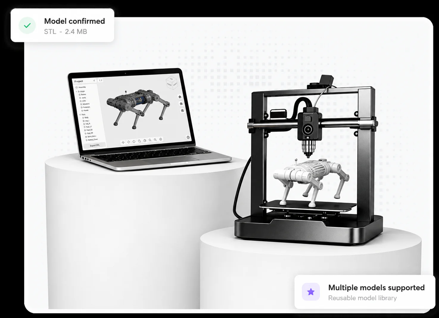
zCAD Online gives additive-manufacturing teams browser-based parametric CAD for functional parts, assemblies, freeform surfaces, design review, versions, drawings, and supported STL export.
A printable mesh is an output, not the engineering source.
Functional 3D-printed parts still depend on controlled dimensions, interfaces, clearances, assembly context, and a model that remains editable after the first physical test.
Engineering pressures
Fit changes after printing
Holes, mounts, wall features, interfaces, and clearances often need revision after the first physical part.
Meshes lose design intent
A frozen export can be difficult to revise when the source dimensions and feature relationships are no longer available.
Prototype feedback fragments
Print observations, assembly issues, and stakeholder comments need to return to one current engineering definition.
Design functional printed parts from editable parametric intent.
Keep geometry, fit requirements, assembly context, review, and supported STL output connected from the first model through the next printed revision.
Functional part design
Create dimension-driven brackets, housings, fixtures, adapters, replacement parts, and other printable mechanical geometry.
Fit and interface control
Keep holes, clearances, mounting points, wall features, and assembly relationships editable as requirements change.
Prototype review and revision
Review the current model in the browser and return approved print, fit, or assembly feedback to the parametric source.
Supported STL handoff
Export supported model data for external slicing and printing while preserving the editable engineering definition.
Move from functional requirement to an external print workflow.
The workflow creates and reviews the engineering geometry before handing supported model data to separate slicing and printing tools.
Define the function
Capture the part purpose, envelope, interfaces, dimensions, clearances, and downstream print constraints.
Build editable CAD
Create the part with parametric features, controlled references, assembly context, and any required freeform surfaces.
Review fit and intent
Inspect the current model with engineering or project participants before committing to another physical iteration.
Export and revise
Send supported STL data to an external print-preparation workflow and return approved feedback to the source CAD.
Project inputs
- Functional and dimensional requirements
- Assembly interfaces and clearances
- Print feedback
Expected outputs
- Editable parametric part geometry
- Reviewable fit and interface context
- Supported STL handoff
Teams involved
- Product and mechanical design
- Prototype engineering
- Additive-manufacturing partners
Connected workflows
Create and Configure CAD
Create editable parametric CAD from requirements, existing geometry, or a blank project—then configure parts, assemblies, and product variants from one reusable design definition.
Review and Collaborate
Review multi-format CAD in the browser and keep engineers, suppliers, clients, and manufacturing teams aligned around the same current 3D design.
Manage Data and Change
Keep CAD projects, versions, permissions, reviews, and design changes connected to the current cloud model.
Document and Deliver
Turn approved 3D product data into model-linked drawings and supported engineering delivery formats.
Product
zCAD Online
Cloud-native 3D CAD software for parametric parts, large assemblies, engineering drawings, and real-time design collaboration in your browser.
Frequently asked questions
What does CAD software for 3D printing do?
CAD software for 3D printing creates the editable engineering geometry behind a printed part. zCAD Online supports parametric features, controlled dimensions, assemblies, freeform surfaces, browser review, and supported STL export for downstream print preparation.
Is zCAD Online a slicer or printer-control application?
No. zCAD Online is used to design and revise CAD geometry. Slicing, support generation, machine setup, material profiles, and printer operation remain in the external additive-manufacturing tools selected by the team.
Why keep a parametric source instead of editing only an STL mesh?
The parametric source preserves dimensions, features, references, and assembly intent. When a printed part needs a new clearance, mount, wall feature, or interface, the engineer can revise the source model and create another supported export.
Can teams review a part before sending it to print preparation?
Yes. Permitted participants can inspect the current browser model, measure relevant geometry, and discuss fit or interface questions before the supported data enters an external slicing and printing workflow.
What should teams verify before manufacturing a printed part?
The responsible team must verify geometry, tolerances, material, wall thickness, orientation, supports, process limits, strength, safety, and the final manufacturing setup. CAD output alone does not approve a part for production use.
Print the iteration without losing the design.
Create functional parts as editable CAD, review the engineering context, and carry supported output into an external printing workflow.
Ready when the project is
Start with the workflow your team can verify.
Open zCAD Online in the browser, or talk with zCAD.ai about the industry workflow on this page.