
AI CAD Tool Guide: Turn Text and Images into CAD Designs
Learn how text-to-CAD and image-to-CAD work, and what to look for when choosing AI CAD tools, from model editability to dimensions and export formats.
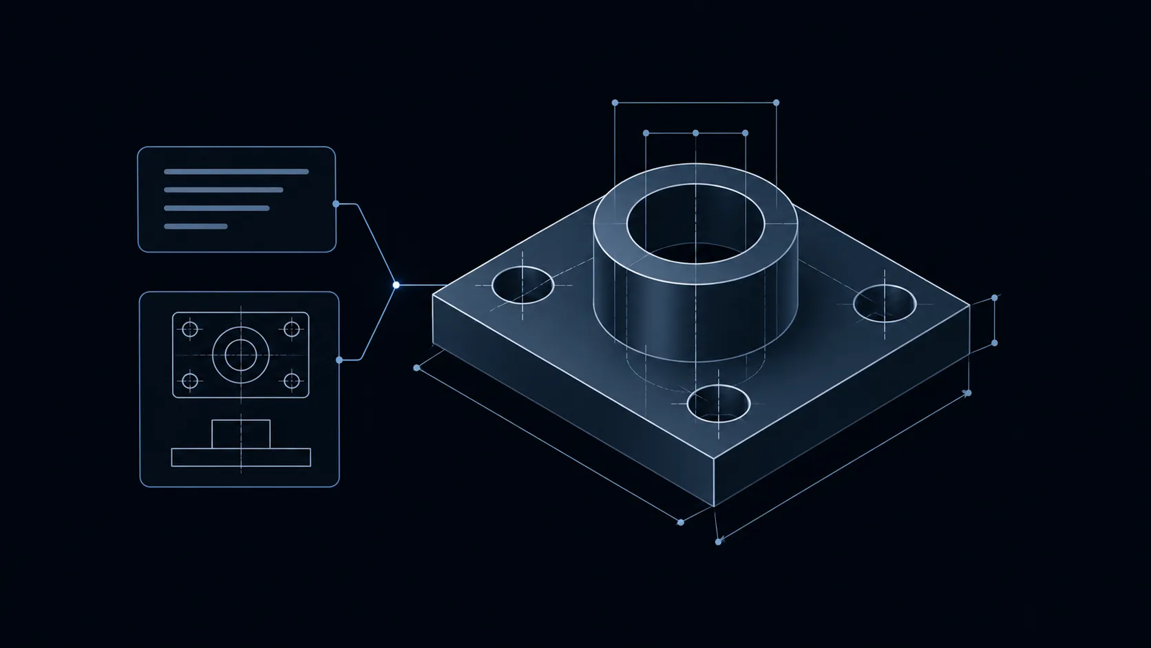
Creating a 3D model traditionally requires time, technical knowledge, and familiarity with design software, so even a simple mechanical part can involve selecting a plane, creating sketches, defining dimensions, and checking the final geometry. For someone who has an idea but limited CAD experience, getting started can be difficult.
AI CAD tools are changing how people approach this process. Instead of building every feature manually, users can describe an object in words or provide a reference image and use AI to generate an initial model.
Text-to-CAD or image-to-CAD gives designers, makers, engineers and beginners another way to move from an idea to a 3D model.
However, not every AI-generated 3D model is suitable for engineering work. The ability to edit dimensions, modify individual features, and work with geometry matters as much as model's initial appearance.
What Is AI CAD Design?
AI CAD design means using artificial intelligence for creating or modifying computer-aided design. It allows users to communicate design requirements through words, images or other inputs rather than relying entirely on manual modeling operations.
For example, for creating a mounting plate 100 × 70 × 10 mm base plate with Centered Ø40 mm boss, and four mounting holes. Traditionally, you would open CAD software, create a sketch, define dimensions, and use modeling features to build the part; but with a text-to-CAD tool, you can describe those requirements in a prompt, and corresponding geometry will be generated.
The type of output depends upon the tool used, some tools generate mesh models that consist of triangles and are intended mainly for visualization. While other tools produce editable CAD geometry that supports further design work.
A model that looks good is not necessarily what is needed, so while choosing the tool, requirements need to be considered, which type of output is needed.
How Artificial Intelligence Is Changing CAD Design
AI CAD introduces another way to interact with CAD systems, instead of manually defining every operation, user can input the requirements and the model will be generated by AI. So some changes that came after using AI in CAD are:
Input methods: The input will be changed, the input can be in form of words, images or other input types as supported by the tool.
Faster initial modeling: AI can generate a starting model without requiring every feature to be modeled manually.
Design changes: User can request changes in dimensions, shapes and other design details.
Lower entry barriers: People with limited CAD experience can explore ideas without first learning every model command.
When a model is created by AI, user still need to check dimensions, geometry, clearances, and manufacturing requirements, whether they are as intended or not.
What Can You Create with an AI CAD Tool?
AI CAD tools can generate a range of 3D designs, from individual mechanical components to multi-part assemblies. Users can create parts such as mounting brackets, enclosures, gears, hinges, and support structures by describing their shapes, dimensions and required features. Some tools can also allow generate assemblies containing multiple components, allowing user to explore how different parts fit together.
Common Input and Output Types
AI CAD software can accept different types of inputs and produce different types of output depending on the tool selected.
Inputs:
The type of input may depend upon the tool used, the input types may include text descriptions that may include dimensions, shapes, and features, reference images or drawing files etc. Multiple inputs can be combined to provide a clearer description of the intended design.
Outputs:
Some tools generate mesh models while some result in editable CAD models. Mesh models provide an approximate dimensions that may look right but they maybe different from the intended design. However, in editable CAD models, the design can be modified further according to the requirements. Dimensions, features can be changed or added newly in editable models. The models can be exported in different formats such as STEP, STL, OBJ, Parasolid etc.
How Text to CAD Works
Text to CAD converts a written description into a 3D CAD model. Instead of manually creating geometry, you can explain what you want to build and AI uses that description to generate a starting design.
From Text Prompt to 3D Model
Consider a simple mounting plate.
You want a mounting plate with cylindrical bosses, and mounting holes. You can describe the design in a text prompt, including the dimensions and important features.
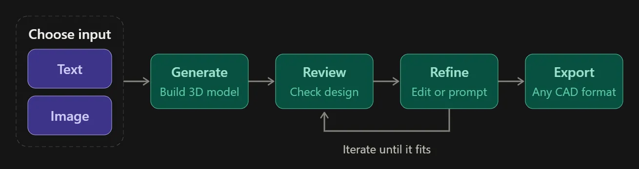
The AI model will process the description and generate a model based on the information provided. A typical workflow will look like this:
1.Describe the part: Explain the purpose, shape, main features, and dimensions such as height, thickness, width and hole diameter.
2.Generate the model: According to the given description, model will be created.
3.Review the result: Review the generated result.
4.Refine the design: Request the changes where the design does not match your requirements.
The first generated model should be treated as starting point, not automatically a finished design.
What Makes a Good Text to CAD Prompt?
A good prompt gives the AI model enough information to understand the intended geometry. For example, for better results, you can use the overall information of the design, shape, dimensions, features involved and how different features are positioned; If there are multiple parts, than the connection between them. A vague description leaves many questions unanswered.
Basic prompt:
Create a rectangular mounting plate with cylindrical bosses.
Improved prompt:
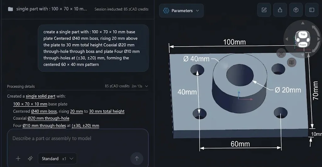
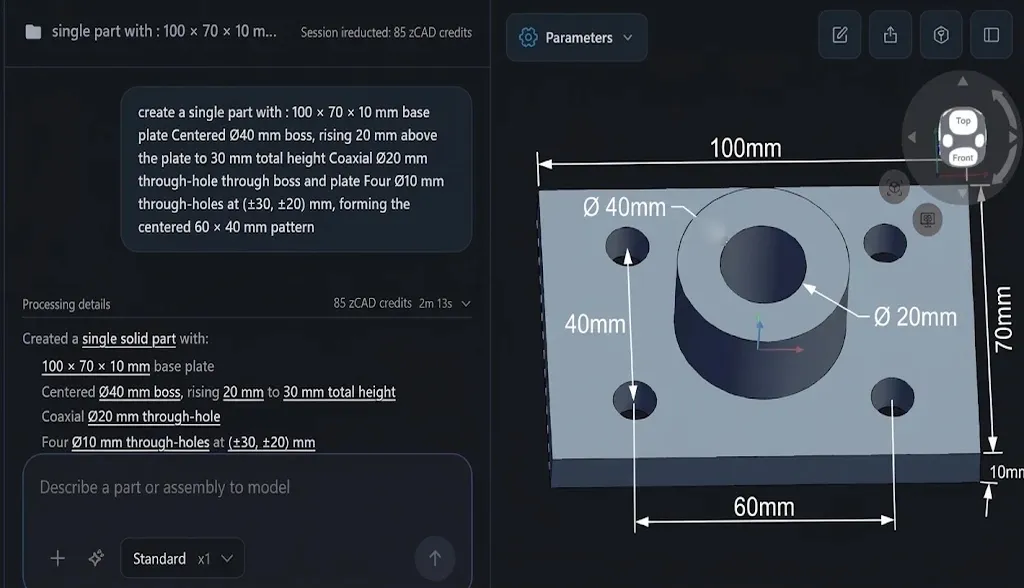
Create a mounting plate with cylindrical bosses, its dimensions are: 100 × 70 × 10 mm base plate Centered Ø40 mm boss, rising 20 mm above the plate to 30 mm total height Coaxial Ø20 mm through-hole through boss and plate Four Ø10 mm through-holes, forming the centered 60 × 40 mm pattern
The created model is just the starting point, you do not need to describe every tiny detail in the first prompt. Start with the main geometry and add more requirements as you refine the model.
Typical Text to CAD Output Formats
Text-to-CAD tools produce different types of 3D output.
Some generate mesh models, these models can be useful for visualization but they do not automatically preserve the original design's parametric feature structure.
Other tools generate editable CAD geometry. Which results in the model that can be modified after creation, the model created initially is just the starting point, and if there is anything that is not according to the requirement, it can be changed. For engineering applications, this difference can have a significant impact on the next steps.
The choice of format depends on what you plan to do with the model. Common formats for 3D output are:
STEP (.step, .stp): Commonly used for exchanging 3D CAD models between different engineering and design applications. It preserves solid geometry and is suitable for further CAD work. However, it generally does not preserve the original software's complete feature history or parametric design tree.
STL (.stl): Stores a model as triangulated surface mesh. It is widely used for 3D printing and slicing workflows. However, it does not preserve editable CAD features, design history, or exact parametric relationships.
OBJ (.obj): Stores 3D geometry as a polygon mesh and can also include information such as surface normals and material references. It is commonly used for visualization, rendering, and 3D content workflows. However, it is not intended to preserve parametric CAD features or engineering design history.
AI Image to CAD Generator: From Sketch or Photo to Model
Text is not the only way to communicate a design idea. Sometimes, showing an existing reference is easier then explaining its shape in words.
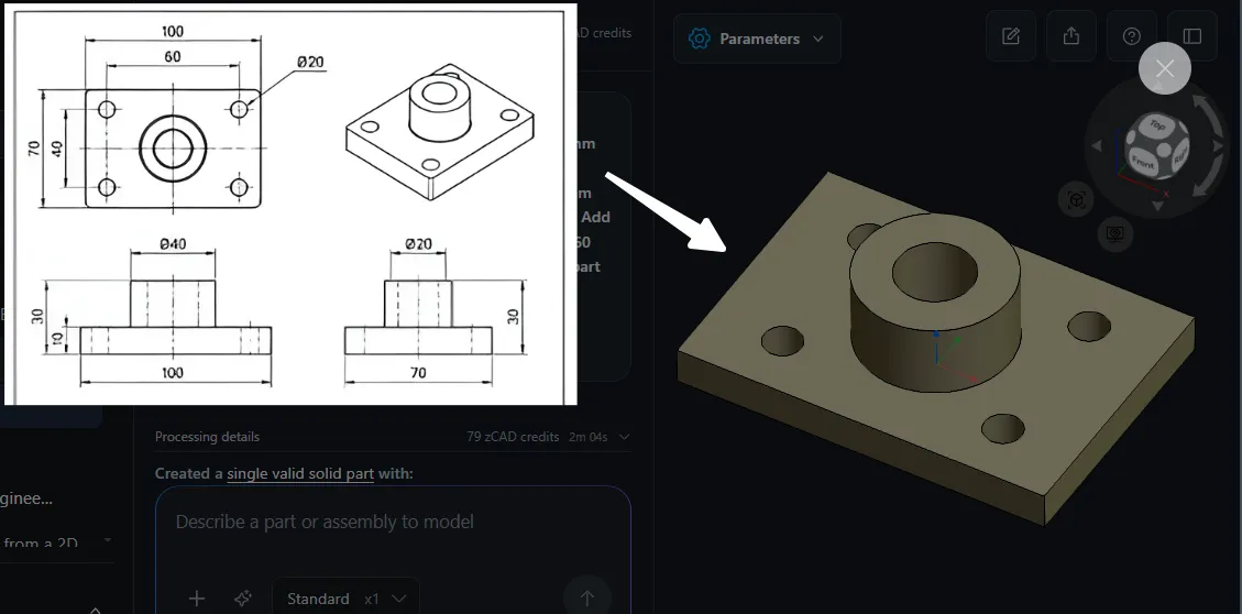
An AI image to CAD generator uses visual input to help create a corresponding 3D model. For example, if you have an image of the model you want to create, you can just share that image as a reference to the CAD model.
How an AI Image to CAD Generator Works
The process begins when a user uploads an image to an AI CAD tool.
The system analyzes the visual information to identify the object's shape and relevant features. Depending on the tool, it may use the image to generate a 3D representation or help construct an editable CAD model.
A typical workflow includes:
1.Upload a reference image
2.AI will analyze the visible geometry
3.An initial CAD model will be generated
4.Inspect the generated model and compare it with the reference.
Further operations depend on the tool used, if editable parametric CAD is used, model can be refined further until it matches the intended design.
Best Types of Images to Upload
The quality of the reference image can affect how well an AI tool understands the intended design. For better results, use images that show:
Clear outlines: The model's boundaries should be easy to distinguish.
Visible features: Holes, slots, cutouts, and other important details should be recognizable.
Simple backgrounds: Avoid unnecessary objects that may confuse image interpretation.
Useful viewing angles: Choose an angle that communicates the model's shape rather than hiding important features. If one image does not show the entire model, provide additional views when the tool supports them.
If exact dimensions matter, include them in the image or provide them separately in text.
When to Use Image to CAD
Image-based CAD generation is particularly useful when the design already exists in visual form.
For example:
You want to recreate a simple component from a reference photograph.
You have an illustration of a product idea that you want to develop further.
You need a starting point for modeling a shape that is easier to show than describe.
You have drawn a rough sketch of a custom enclosure.
Text to CAD vs Image to CAD
Both methods help users move from an idea to a CAD model, but they communicate design requirements differently.
Text input is useful when dimensions, measurements, and functional requirements are already known. Image input is useful when the intended model is easier to communicate visually.
Key Differences at a Glance
Comparison | Text to CAD | Image to CAD |
Input | Written description | Sketch, photograph, or illustration |
Main strength | Communicating dimensions and design requirements | Communicating visual shape |
Best-fit scenarios | Parts with clearly defined dimensions and features | Designs that are easier to show than describe |
Main limitation | Requires clear descriptions and suitable terminology | Hidden geometry in image and exact dimensions may be unknown |
Which Input Method Should You Choose?
Choose text to CAD when you know the measurements and features your part needs. Choose image to CAD when you already have a sketch or visual reference.
The two methods can also work together. For example, you can start with an image to communicate the overall shape and then use text instructions to specify dimensions, hole positions, and other design details.
Types of AI CAD Software
Not every AI CAD tool works in the same way. Some focus on generating models from written descriptions, while others use images or integrate AI features into existing CAD environments.
Understanding the main categories makes it easier to select software that matches your requirements.
Text to CAD Generators
These tools focus on converting natural-language descriptions into 3D models. Users describe the model, specify dimensions, features, and let AI generate geometry. They are useful when someone understand what they want to create but prefer not to build the entire model manually.
Image to CAD Generators
These tools use visual references as their starting point. They are useful for turning sketches, photographs of models into an initial 3D design. Their effectiveness depends on image quality, the complexity of the model and the software's ability to interpret geometry.
All-in-One AI CAD Tools
Some tools support multiple input methods within one environment.
Users can generate models from both text or images. This approach can reduce the need to move between separate generation and editing applications.
AI Features Inside Traditional CAD Software
Another category includes conventional CAD platforms that incorporate AI into existing design workflows.
These features may help with design suggestions, automation, modeling assistance, or other repetitive tasks.
Unlike dedicated text-to-CAD generators, they may still require users to work with the traditional CAD interface and understand its modeling operations.
How to Choose an AI CAD Tool
Choosing AI CAD software requires more than comparing how quickly different tools generate a model.
The most important question is whether the software can produce the type of output you need and support the work you plan to do afterward. Consider these factors before making a decision.
Supported Input Methods
Start by checking how you can provide design requirements.
Does the software support text prompts, image uploads, or both?
If you regularly work from sketches, an image input option may be important. If your designs are based on measurements and engineering specifications, text input may be more suitable. However, having both options can provide greater flexibility.
Export Formats and Compatibility
A generated model is only useful if you can move it into the next stage of your workflow. Check which formats the software supports. Common formats include STEP, STL, OBJ, parasolid etc.
Editability of Generated Models
This is one of the most important considerations. A generated model may look accurate but still be difficult to modify. Before choosing a tool, find out whether the output preserves meaningful dimensions, features, constraints, and assembly relationships.
For example, consider a product enclosure that needs a wider mounting section. Can you change the relevant dimension without rebuilding the entire model?
Editable parametric geometry makes these changes more practical.
Ease of Use and Generation Speed
A simple interface can make AI CAD more accessible, especially for people who are new to CAD software.
However, generation speed should not be the only deciding factor. A tool that produces a model quickly but requires extensive corrections may not save much time overall.
Look at the complete workflow, including generation, inspection, refinement, and export.
Pricing and Free Options
Compare free usage limits, generation credits, subscription plans, and export restrictions. Some tools offer a limited number of free generations, while others provide access to additional features through paid plans.
Check whether the features you need are available in the plan you intend to use.
Templates, Tutorials, and Support
Documentation and examples can make a considerable difference when learning a new AI CAD tool. Look for practical tutorials, example models, sample prompts, and guidance on refining the generated designs.
The resources can help you understand what the software can produce and how to communicate more detailed requirements.
AI CAD with zCAD. AI: Text to CAD and Image to CAD in One Tool
For users looking for a way to create editable CAD models from written description or visual references, zCAD offers a connected AI and parametric workflow. The platform includes two products: zCAD. AI and zCAD. Online.
zCAD. AI focuses on generating editable CAD parts and assemblies from text descriptions and reference images. zCAD. Online provides the modeling environment for developing those designs further, or preparing engineering drawings.
What Is zCAD. AI?
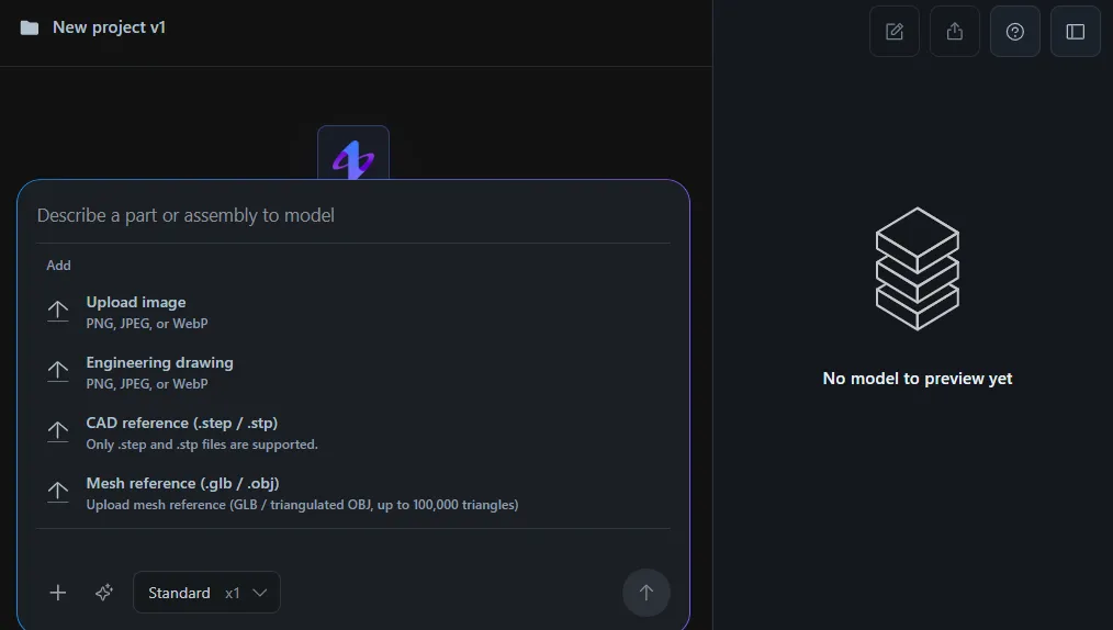
zCAD. AI is an AI CAD platform that turns design requirements into editable CAD geometry. Users can describe the intended part or assembly and provide the necessary design information. The AI generates an initial model that can be reviewed and refined. Input can be given in form of text as well as in form of images at the same time.
An important distinction is that zCAD. AI generates an editable model, instead of generating meshes. Its generated models can carry dimensions, geometric constraints and assembly mates. The model can be created in zCAD. AI and can be further edited in zCAD. Online.
Key Features of zCAD. AI
Some of the key capabilities include:
Text-based generation: Describe a part or assembly using natural language.
Image-based generation: Provide a reference image to communicate the intended design.
Editable geometry: Work with editable CAD geometry rather than relying only on output meshes.
Multiple components: Generate multiple components in an assembly and their assembly relationships.
Design refinement: Review the generated model and make changes to its dimensions and geometry.
Connected CAD workflow: Continue working with the generated model in zCAD. Online.
Text to CAD with zCAD. AI
With zCAD. AI, you can begin by describing the part you want to create.
For example, Create a mounting plate with cylindrical bosses, its dimensions are: 100 × 70 × 10 mm base plate Centered Ø40 mm boss, rising 20 mm above the plate to 30 mm total height Coaxial Ø20 mm through-hole through boss and plate Four Ø10 mm through-holes, forming the centered 60 × 40 mm pattern
The provided information will be used to create the model. After the model is generated, inspect the result to make sure the geometry reflects your requirements. If something needs changing, it can be done by giving further prompts; model can also be modified by opening it in zCAD. Online.
Image to CAD with zCAD. AI
You can also start with the reference image instead of describing the entire design from scratch. This is useful when you already have a visual idea of the part but need help turning it into CAD geometry.
For example, you might upload a sketch of a mechanical component and use additional text instructions to clarify its dimensions, hole positions, or other design requirements.
The image communicates the overall shape, while text can provide information that may not be visible in the reference. Once generated, the model can be reviewed and further developed through the connected workflow.
Who Is zCAD. AI For?
The platform can be useful for several types of users:
Makers: Create custom components for personal projects.
3D printing users: Develop editable parts and make dimensional changes before preparing models for printing.
Product designers: Explore product concepts and develop initial component geometry.
Mechanical engineers: Generate starting point for parts and assemblies that require further engineering work.
Hardware teams: Explore component designs and develop product concepts into more structured CAD models.
Users still need to verify important engineering requirements, including dimensions, material selection, clearances, and manufacturing suitability.
AI CAD vs Traditional CAD Software
Traditional CAD provides direct control over the modeling process. Users create sketches, apply constraints, define features, and build geometry through dedicated tools.
AI CAD introduces another way to begin the process by changing the description or images into an initial model, in this way that model created is just the starting point, Instead of creating everything manually.
Speed and Learning Curve
Traditional CAD requires users to learn the software's interface and modeling methods. Even simple designs may involve several operations. AI CAD can reduce the effort required to create an initial model. Users can describe a required model rather than constructing every feature manually. However, complex designs still require careful review and refinement.
Cost and Accessibility
Traditional CAD software can involve installation requirements and a learning curve. Browser-based AI CAD tools can make certain design tasks more accessible. Users can begin with a description or image without first learning an entire set of modeling commands.
Actual costs and available features vary between platforms.
Using AI CAD and Traditional CAD Together
The two approaches do not need to replace one another. AI CAD can help generate an initial part or assembly, while traditional parametric CAD provides the tools to develop, inspect, and document the design.
For example, a designer might generate a mounting assembly using AI, then open it in parametric CAD environment to adjust dimensions, check component relationships, and prepare engineering drawings.
This combined workflow allows users to benefit from faster initial generation while retaining control over the final design.
AI CAD Use Cases
AI CAD has applications across different industries and types of design work. Its usefulness depends on the complexity of the model, the accuracy of the input, and the editing capabilities of the software.
Mechanical Parts and Prototyping
Designers can use AI CAD to generate initial models of brackets, mounting plates, supports, and other mechanical components.
These models can provide a starting point for prototyping and further development.
Product Design and Concept Modeling
Product designers often explore several shapes and configurations before settling on a final design.
Text and image inputs can help communicate early ideas and generate initial component geometry without manually constructing every version.
3D Printing
AI CAD can help users create custom parts for 3D printing, including holders, adapters, enclosures and replacement components. However the model should be checked for dimensions, wall thickness, and other requirements before printing.
Architecture and Interior Design
AI-based design tools can help explore layouts, spatial concepts, and visual forms.
For detailed architectural or construction work, users still need appropriate software, accurate measurements, and professional verification. A generated concept should not automatically be treated as a construction-ready design.
Education and Maker Projects
For students and beginners, AI CAD provides another way to explore how written requirements and visual ideas translate into 3D geometry. It can also help makers experiment with custom designs while gradually becoming familiar with CAD concepts.
How to Get Started with AI CAD: Step-by-Step
Getting started with an AI CAD tool does not require a complicated project. A simple mechanical component is a good way to understand the workflow. The step by step process is:
Step 1: Choose Your Input (Text or Image)
Decide how you want to communicate the design. If you already know the dimensions and features, start with the text description. If you have a sketch or reference photograph, use an image-based input option.
You can also combine both methods when the visual reference does not communicate every requirement.
Step 2: Describe or Upload Your Design
Provide the information needed to generate the part. For text input, include the part type, dimensions, and important features. For image input, select a clear reference that shows the model's main geometry.
Step 3: Generate and Review the Model
Generate an initial model and inspect it from different angles. Check whether the overall shape matches your requirements. Pay attention to the dimensions, hole locations, component connections, and other important features. Model details may need to be checked because it need to be make sure that the model not only looks right but is according to the intended design.
Step 4: Refine Your Design
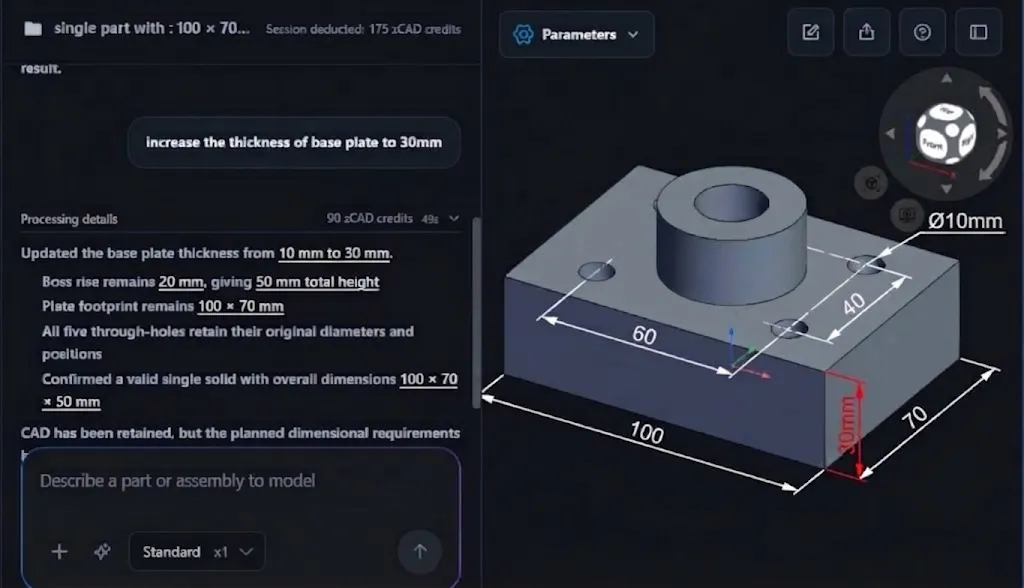
If the generated model needs changes, provide specific instructions. For example, increasing the thickness of part created from 10 mm to 30 mm. Instead of describing the entire part again, request a targeted change to the thickness. Also check the other dimensions remain unchanged.
Before enhancement | After enhancement |
|
|
Step 5: Export Your CAD File
Once you are satisfied with the model, prepare it for the next stage of your workflow. Choose an appropriate export format based on the requirements. For example, STEP, STL, OBJ etc.
Check the export options and verify that the exported file opens correctly in the intended application.
Prompt Tips for Better AI CAD Results
The quality of instruction given can affect the quality of generated model. A clear description of the important geometry and dimensions gives the AI a better starting point.
A Simple Prompt Formula
A useful way to structure a text-to-CAD prompt is:
Part type, overall dimensions, main features, feature positions and important relationships.
For example:
"Create a mounting plate with cylindrical bosses, its dimensions are: 100 × 70 × 10 mm base plate Centered Ø40 mm boss, rising 20 mm above the plate to 30 mm total height Coaxial Ø20 mm through-hole through boss and plate Four Ø10 mm through-holes, forming the centered 60 × 40 mm pattern."
This provides a clear starting description without unnecessary detail.
Prompt Examples: Basic vs Better
Basic:
"Create a rectangular enclosure."
Better:
"Create a rectangular electronics enclosure measuring 120 × 80 × 40 mm, with 3 mm wall thickness, a removable top cover, and four mounting holes near the corners."
The second prompt explains the size, structure, and important features.
Tips for Better Image Inputs
When using an AI image to CAD generator, consider the following:
Use a clear image with visible object boundaries.
Avoid background with distracting objects.
Include dimensions wherever possible.
Choose views that reveal important geometric features.
Provide additional images if different sides of the object are important.
If there is a feature that is hidden in image, explain that in text description.
A combination of visual reference and written dimensions can provide a more complete description of the intended design.
Conclusion
AI CAD tools are making it easier to move from design ideas to 3D models. With text-to-CAD, users can describe parts and dimensions in natural language. With image-to-CAD, sketches and reference images can provide a starting point for model generation.
However, the quality of an AI CAD tool should not be judged by generation speed or visual appearance alone. Editability, dimensional control, geometry, and compatibility with CAD workflows are equally important.
For users who want to move beyond visual concepts and develop actual CAD designs, zCAD brings text-based and image-based generation together with editable parametric modeling.
The most practical approach is to use AI to accelerate the initial design process, then review and refine the resulting model before relying on it for prototyping or manufacturing.