
How to Use AI CAD to Improve Your Design Workflow
Learn how to use AI CAD to turn descriptions into 3D models, check dimensions, refine designs, and prepare functional parts for printing or manufacturing.
Introduction to AI CAD
Designing a 3D part takes many steps: understanding the requirements, creating the geometry, setting dimensions, and checking that whether the created model meets the requirements. When you are starting from an idea, even a simple component takes time to model.
This is how AI in CAD is changing the early stages of design, it provides another way to begin, instead of building every feature manually, you can describe the part in plain language and AI CAD will generate an initial model. You can then review the result, make adjustments and continue working in a CAD environment.
What is AI CAD?
AI CAD means using artificial intelligence in computer-aided design. You can describe a part with text, images or other references.
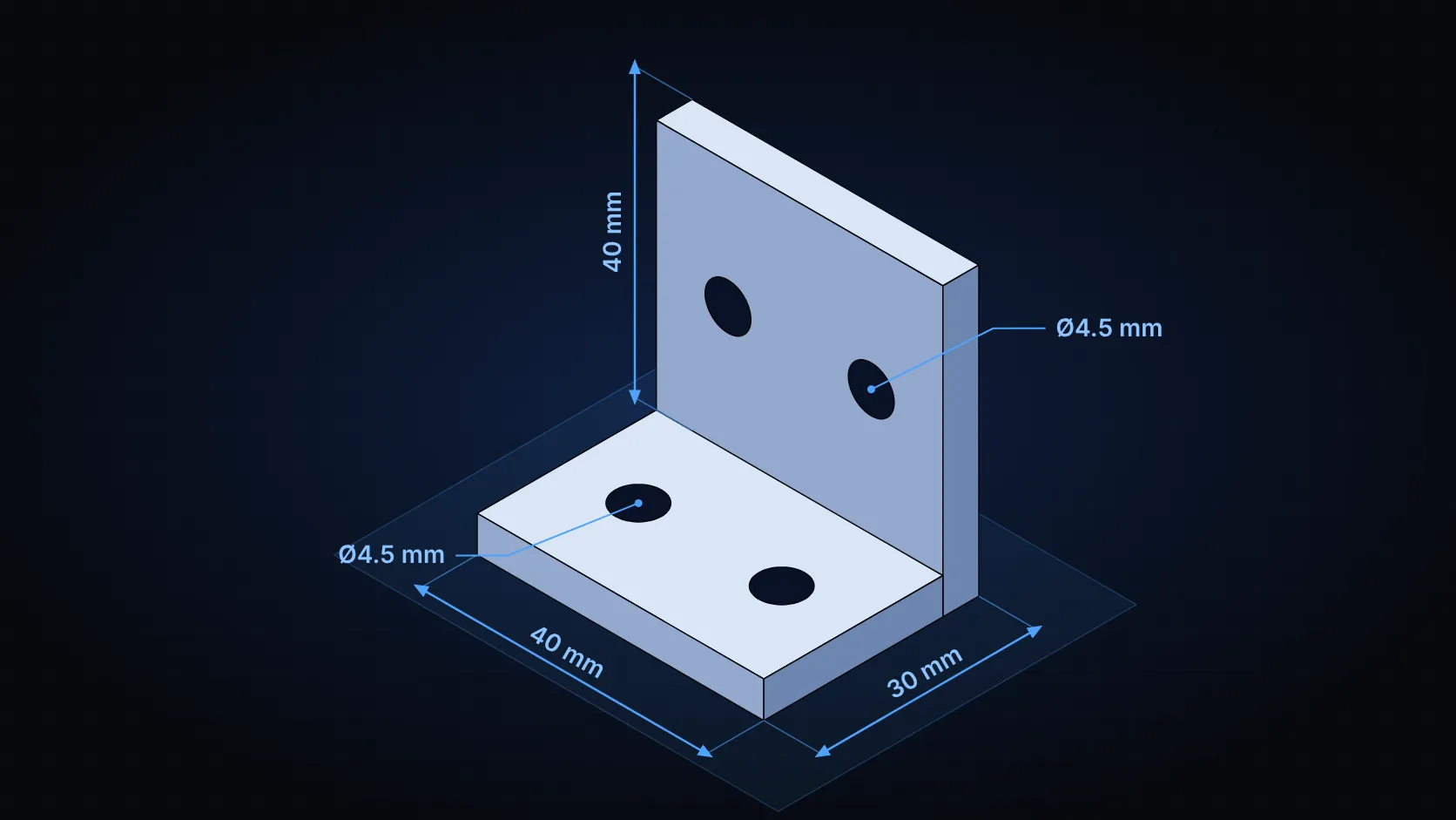
For example, for a mounting bracket, you might give its length, width, thickness, hole positions, and mounting requirements. AI CAD generator will use that description to create an initial 3D model.
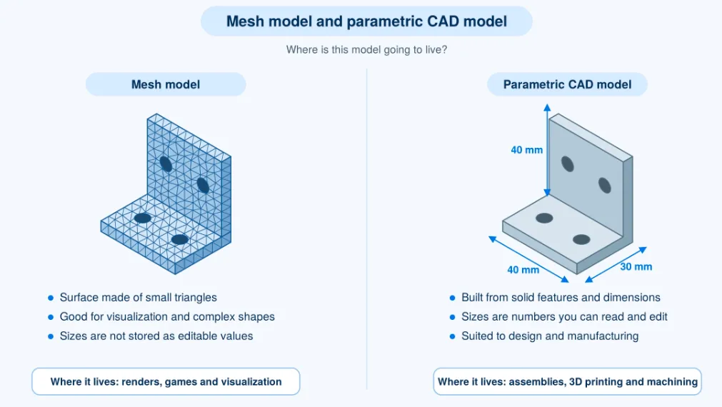
The output varies and depends upon the tool used. Some tools generate mesh models which look right but their sizes are approximated while others can produce editable CAD geometry, where dimensions and features can be modified.
Understanding this difference is important when choosing AI CAD software for a project.
Where AI Fits into the CAD Design Process
AI can be useful at several points in the CAD design process, from creating an initial model to refining the final design.
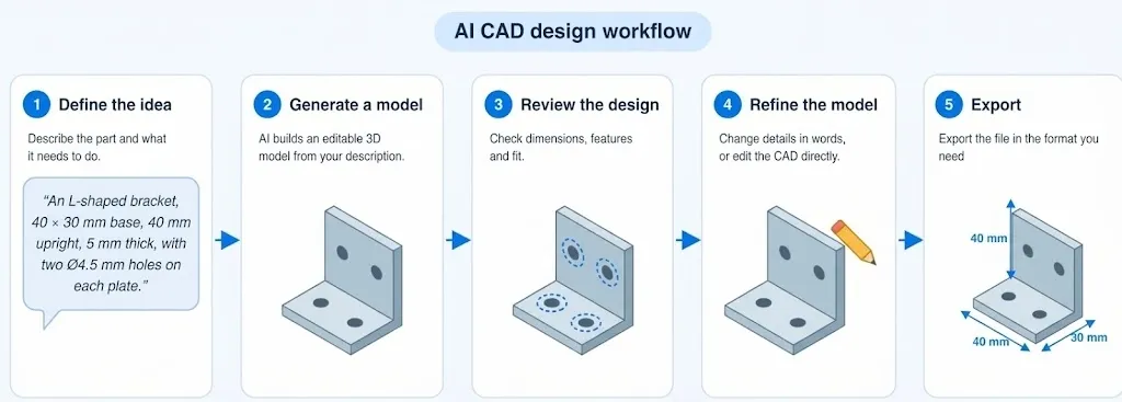
A typical AI CAD design workflow might look like this:
1.Define the idea: Describe the part, its purpose, and the main design requirements.
2.Generate an initial model: Use an AI CAD tool to create a starting point from the description or supported reference inputs.
3.Review the design: Check the overall shape, dimensions, openings, and connections.
4.Refine the model: Adjust the model using the available AI and CAD tools, After refining confirm that the part fits its intended application and manufacturing requirements.
5.Export: Export the file in the format you need.
Benefits of Using AI CAD Software
AI CAD software makes the design process becomes more accessible and users can explore ideas without beginning every model from scratch.
Getting from an Idea to an Initial Model
Starting a model from scratch might be challenging, particularly if you are not familiar with every CAD operation. An AI CAD tool gives you a starting point: describe the component and its important features, and generate an initial model.
For example, a user designing a small electronics enclosure could specify its overall dimensions, wall thickness, mounting holes, and openings for connectors. The generated model provides geometry to review and refine instead of requiring every feature to be created manually from the beginning.
The result still needs to be checked, but this approach can help turn an early concept into something more concrete.
Exploring Design Variations
A design often changes as requirements become clearer. You might need a wider mounting base, a different hole pattern, or an opening in another position.
With an AI CAD tool, you can describe the changes, and generate an updated model. Review the result to check whether the changes match your requirements.
For example, for designing an L-shaped mounting bracket, you first generated a bracket with two mounting holes on its base. Later, you decide that four holes would provide more flexibility. You can update your prompt and generate a revised model.
Making Repetitive Modeling Tasks Easier
Many parts contain familiar features such as holes, slots, and mounting tabs. Describing these features can provide a quicker starting point than creating every element manually.
AI can also help when there are variations required in the design. Rather than treating each variation as an entirely new design, you can use the original requirements as a reference and describe the changes. However, detailed mechanical features may still require manual refinement.
AI CAD Tools and Features
Not all AI CAD tools work in the same way. Some focus on generating 3D shapes, while others aim to produce CAD geometry that can be edited and refined.
Different Types of AI CAD Tools and How They Work
AI is being used in CAD workflows in several ways:
Text-to-CAD tools: Generate 3D geometry from written description of a part or assembly.
Image-based modeling tools: Use a reference image for generating a 3D model.
Design exploration tools: Help explore variations based on specified requirements or constraints.
AI features within CAD software: Support particular tasks within an existing CAD environment.
These categories can overlap. A tool may support more than one type of input or combine AI generation with conventional CAD operations.
AI CAD Generators Explained
An AI CAD generator interprets the information provided by a user and uses it to create a model. The input might describe the overall shape, dimensions, features, or relationships between components.
For example, a prompt for mounting plate could specify overall length and width, plate thickness, number and diameter of mounting holes or any additional features.
The generator will use these requirements to produce an initial model. More detailed descriptions generally provide clearer design direction.
What to Look For: Editable Geometry, Dimension Controls, and Export Formats
When evaluating AI CAD software, consider what you can do with the generated model after it is created.
Editable geometry: Check whether the output is a mesh model or editable CAD geometry. A mesh can represent the object's appearance, but parametric CAD provides features and dimensions controls.
Dimension controls: Look for ways to inspect and modify important measurements, such as hole diameters, wall thickness, and component spacing. These controls are particularly useful when design must fit existing hardware.
Export formats: Check which file formats are supported by the software. A workflow involving other CAD applications, engineering drawings or manufacturing may require specific formats.
Practical Applications of AI CAD
AI CAD can support different design tasks by turning descriptions of parts, dimensions, and features into initial 3D model.
Creating Brackets, Mounts, and Enclosures
Brackets, mounts and enclosures are common examples that can be described through dimensions and feature positions: base shape, thickness, holes, slots and openings. An electronics enclosure, for example, might need wall thickness, connector openings and mounting points for a circuit board.
Designing Functional Parts for 3D Printing
AI CAD can help create functional parts such as replacement knobs, small mounts, brackets and custom adapters. A replacement knob, for example, needs an exact outer diameter, height and D-shaped shaft opening, since a model with the wrong dimensions won’t fit the equipment.
Before printing, check dimensions, clearances and wall thickness for your printing process.
Example Workflow: From a Part Description to a Refined CAD Model
Consider a simple L-shaped mounting bracket that attaches a component to a frame.
Step 1: Describe the part: Specify the dimensions, thickness, and the mounting holes.
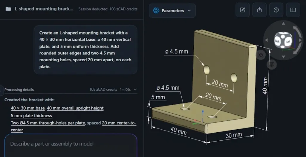
Step 2: Generate the model: Enter the description, an initial model will be created, then review the resulting bracket.
Step 3: Check the important features: Inspect the overall dimensions, hole diameters and spacing.
Step 4: Refine the model: If something looks wrong, revise the prompt or use the available CAD tools to fix it.
Step 5: Validate the result: Compare the model with the actual requirements and its suitability for intended manufacturing process.
Integrating AI CAD into Your Workflow
A clear task and careful review of generated geometry can help you get more useful results from AI CAD.
Choose a Suitable Design Task
Start with a part that has a clear purpose and well-defined geometry. For example, a mounting bracket, simple enclosure, or a replacement component. A simpler design makes it easier to evaluate how well the tool handles your requirements.
Define Dimensions, Features, and Constraints
Before generating the model, identify the information it needs: overall dimensions and thickness, hole diameter, positions and spacing, slots, cutouts, connection points etc. Use specific parameters where possible, for example, describing the hole diameters and their center-to-center spacing.
Generate and Check the Initial Model
Enter the description and generate the model. A result that resembles the part isn’t necessarily correct. So compare the generated geometry against your requirements. Check overall shape, dimensions, feature positions, and component interfaces. If something is missing or incorrect, identify the issue before moving on.
Refine the Design with Available AI and CAD Tools
Most practical designs need some refinement, such as changing a dimension, repositioning a hole, adjusting an opening, or modify the relationship between components.
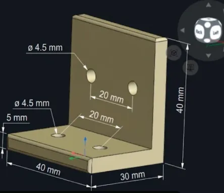
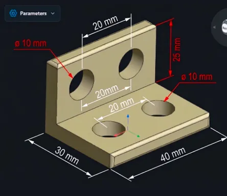
Use AI tool to request supported changes and the CAD environment to inspect and refine the geometry with its available tools.
Before refinement | After refinement |
|
|
Prompt: Create an L-shaped mounting bracket with a 40 × 30 mm horizontal base, a 40 mm tell vertical plate, and 5 mm uniform thickness. Add rounded outer edges and two 4.5 mm mounting holes, spaced 20 mm apart, on each plate. | Prompt: Modify the existing L-shaped mounting bracket by reducing the vertical plate height from 40 mm to 25 mm and increasing all four mounting hole diameters from 4.5 mm to 10 mm. Keep the 40 × 30 mm horizontal base, 5 mm uniform thickness, rounded outer edges, and 20 mm hole spacing unchanged. |
Validate Fit and Manufacturing Requirements Before Export
A generated CAD model is not automatically ready for manufacturing. Check that:
The dimensions match the requirements
Holes, slots and interfaces are correctly positioned
Connected components have sufficient clearance
Manufacturing requirements have been considered
For assemblies, also check how the individual parts fit and interact. The required validation will depend on the part, its intended use, and the manufacturing process.
Conclusion
Recap: Where AI CAD Can Help and What Still Needs Checking
AI CAD can help turn a written idea into an initial 3D model, explore design variation and reduce some repetitive modeling work. The generated model is a starting point, so check its geometry, dimensions and manufacturing requirements before relying on it.
Start Small and Evaluate the Results in Your Own Workflow
Start with a simple part, describe its requirements, and evaluate how well the tool handles the task. As you become familiar with the workflow, you can explore more detailed components and assemblies.