
Parametric CAD: What Is Parametric Modeling and How It Works
Learn how parametric CAD works and differs from direct modeling. See how changing dimensions helps you customize parts for 3D printing.
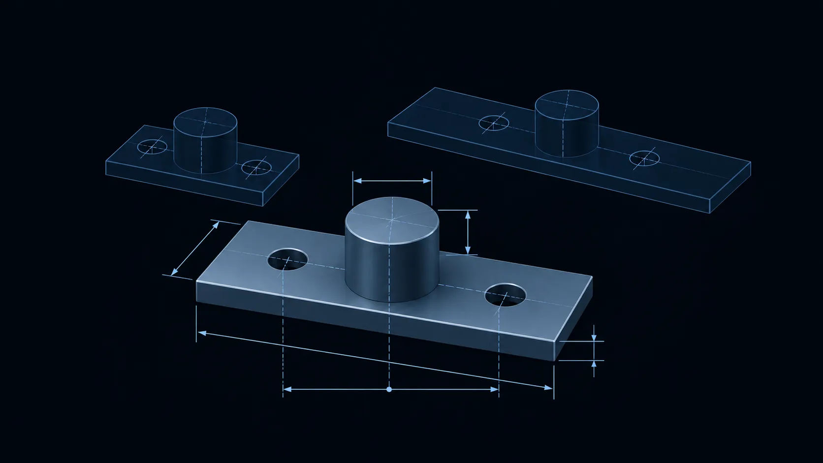
Parametric CAD is a way of creating 3D models using dimensions, constraints, and relationships that control the geometry of a design. Instead of rebuilding a part whenever something changes, you can adjust a parameter and let the model update according to the requirements you have defined.
What Is Parametric Modeling?
Parametric modeling is a method of creating and modifying 3D geometry through a set of defined values and relationships. These values, known as parameters, can include dimensions such as length, width, height, diameter and thickness. Constraints and feature relationships determine how different parts of geometry interact with each other, and how they behave when values are changed.
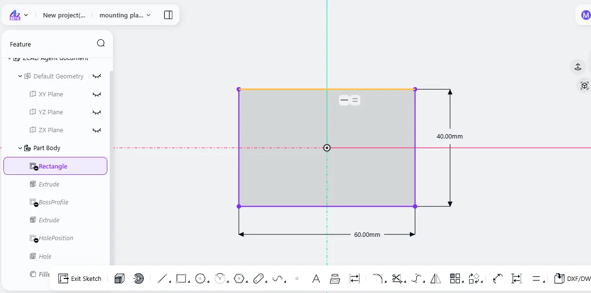
For example, if you are designing a mounting plate that is 60 mm long and 40 mm wide, with two mounting holes positioned equally around its center. In a parametric model, you can define the plate dimensions and the relationship between the holes, if you increase the plate length to 70 mm, the model can update while keeping the holes equally spaced and maintaining their intended position.
This is what makes parametric modeling different from simply creating a shape and adjust its surfaces. The model contains the information about how it was created and how its geometry should respond to changes.
Parametric CAD is commonly used in mechanical design, product development, and manufacturing where parts often need revisions or different size variations. It is also useful for beginners who want to create designs that can be adjusted without starting from scratch.
Parameters, Constraints, and Features
Three elements form the foundation of parametric modeling: parameters, constraints, and features.
Parameters: These are the values that define the dimensions or properties of the model. Common examples include: length, width, height, wall thickness, fillet radius and distance between two features. Parameters can be changed individually.
Constraints: Constraints define how geometry behaves and how different elements relate to one another. They help maintain the intended shape and position of sketch elements. Common geometric constraints include: horizontal and vertical, coincident, parallel, perpendicular, equal, concentric etc. Dimensional constraints define exact values such as 10 mm distance between two points.
Features: features are individual operations used to build a 3D model. Different features work together to capture the design intent. A feature may add material, remove material, or modify an existing model. Common examples include: Extrude, revolve, hole, chamfer and pattern.
For example, when designing a mounting plate, you might want two holes to remain equally spaced and centered even when the plate becomes wider. Instead of positioning each hole independently, you can define relationships that keep them aligned with the center, so that when plate dimensions change, the model can preserve those relationships.
This is one of the main advantage of parametric modeling, you define not only what the part looks like, but also how it should behave when you make changes.
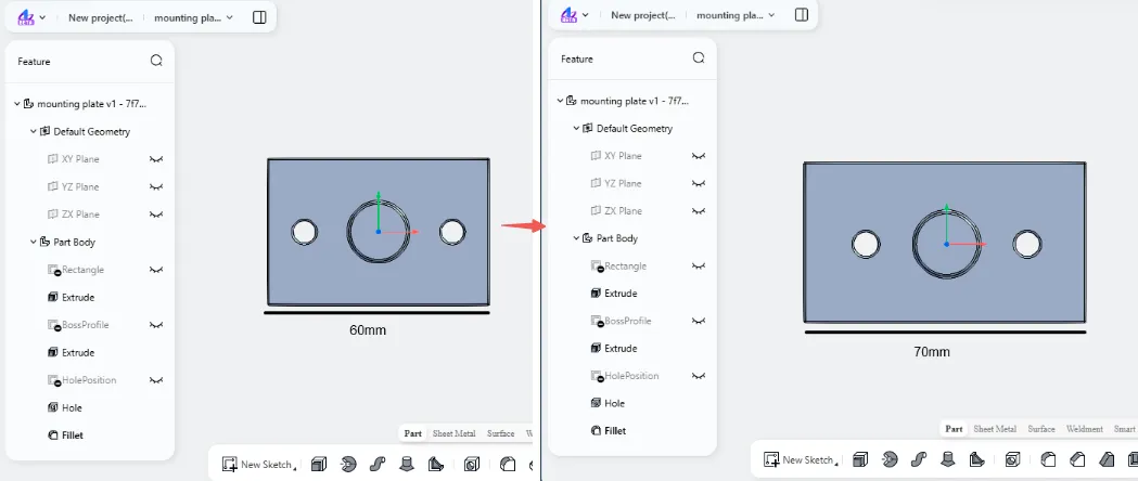 Example shown in zCAD. Online
How Parametric CAD Works
Parametric CAD works by building a model through a sequence of connected operations, rather than treating the finished shape as one fixed object, the software maintains information about its construction. This makes it possible to return to earlier operations and adjust the design without rebuilding the entire part. Dimensions and constraints define how the model behaves.
From Sketch to Parametric 3D Model
Most feature-based parametric workflows begin with a 2D sketch. A sketch defines the initial geometry that will be used to create a 3D model. For example, consider a simple mounting plate, for a 3D model, you can create a sketch, add relevant dimensions and constraints where needed, then you can apply any 3D feature for example, extrude, revolve etc, then According to the requirements, more design details can be added such as holes, fillets etc, then you need to review the model, check the dimensions and relationships to make sure the geometry matches the intended design.
The resulting part contains the sequence of modeling operations and the information used to define them. If the plate needs to become longer, its sketch can be edited or if mounting holes need to be larger, you can change their diameter through relevant feature settings.
The geometry is built and then is modified through parameters, constraints, and dependent features.
The Feature Tree and Design History
A feature tree is an organized record of the operations used to create a parametric model. Depending on the CAD software, it may also be called structure tree, design tree, or feature history.
The feature tree makes it easier to understand how a part was constructed. Feature tree also need to be managed carefully. If later features depend on a feature that changes or is deleted, an edit may cause an operation to fail. Through feature tree, another designer can inspect the modeling steps and edit the relevant operation.
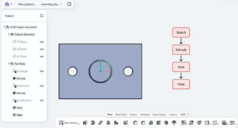
For example, for a mounting plate, feature tree might contain the following sequence: sketch (defines the outline), Extrude (creates the plate thickness), Hole (adds mounting holes), Fillet (round selected edges). Each operation appears in feature tree.
Parametric vs Direct Modeling
Parametric modeling and direct modeling are two approaches to creating and modifying 3D geometry in CAD software. Both can produce useful models, but they can differ in how design changes are managed.
Comparison | Parametric Modeling | Direct Modeling |
How editing is done? | Changes dimensions, parameters, constraints or feature settings | Modifies geometry directly by moving or adjusting faces, edges, and surfaces. |
Design intent | Can preserve defined relationships between dimensions and features. | Does not automatically preserve defined dimensional and geometric relationships when the model is edited. |
Design history | Maintains an editable feature history, such as sketches, extrusions, and holes, that controls how the model is built and updated; It records the modeling operations and their dependencies. | Does not rely on an original sequence of parametric features; edits are applied directly to existing geometry. |
Design flexibility | Useful when dimensions and relationships need to remain consistent through revisions | Useful for quick geometric changes and exploring different shapes. |
Best-fit scenario | Dimension-driven parts, repeatable designs, and models requiring frequent revisions. | Quick shape adjustments, concept exploration, and modifications to existing geometry. |
When should you use each approach?
Parametric modeling is a good choice when you are designing parts that depend on specific dimensions, need repeated revisions, or must maintain consistent relationships. It is particularly useful for adjustable brackets, mechanical components, product enclosures, and parts that come in different sizes.
Direct modeling can be more convenient when making a quick adjustment to an existing model, particularly when the original parametric feature history is unavailable, such as with many imported STEP models. For example, if you receive an existing mounting plate and only need to change the position of one hole, direct editing may be more straightforward.
The right choice of modeling depends on the design requirements, the type of geometry, and how much control you need over future changes.
What Does Parametric Mean in 3D Printing?
In 3D printing, parametric modeling means creating a printable design whose dimensions and geometric relationships can be adjusted without building the entire part.
This is particularly useful because printed parts often need changes after an initial test. A component may be too large for its intended space, a mounting hole may not line up, or two parts may fit too tightly when assembled.
With a parametric model, you can adjust the relevant dimensions and generate the revised version while retaining the relationships built into the design.
Parametric Designs for Customizable Prints
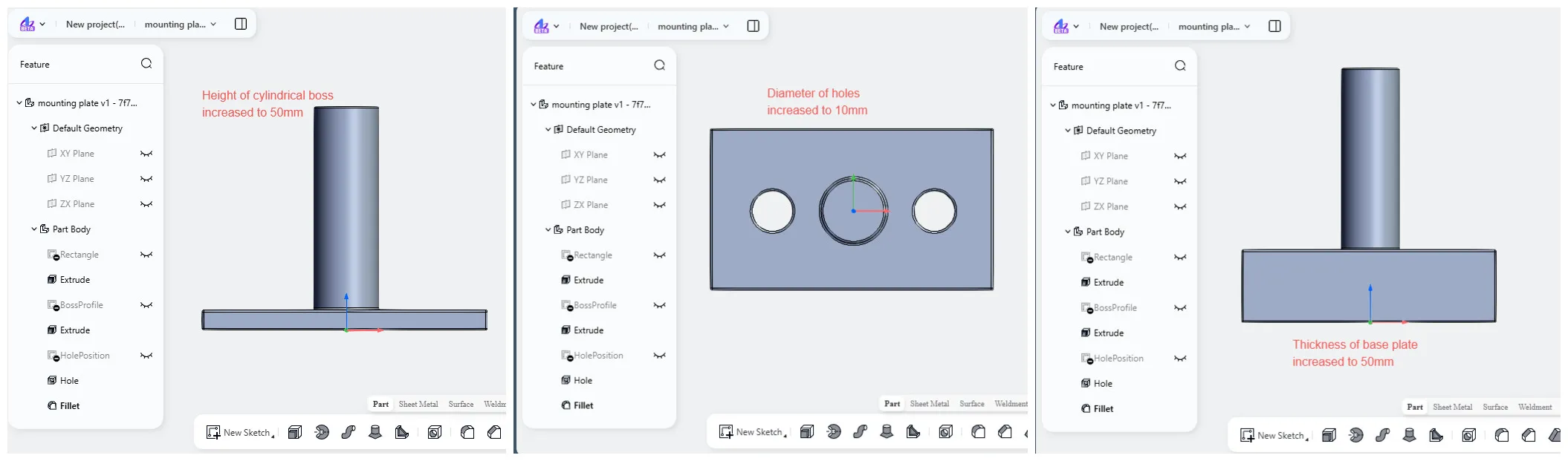
Consider a mounting plate with a base length of 60 mm, a width of 40 mm, and a thickness of 5 mm. The plate has two holes of diameter 6 mm positioned symmetrically about the center and a cylindrical boss at the center with diameter of 16 mm, and 10 mm in height. All edges have a 0.5 mm fillet.
The same model can also be used to create different design variations. For example, mounting plate might need to fit a different assembly. Adjusting the relevant parameters allows you to reuse the original design as a starting point. You can also create different versions of the plate by changing individual dimensions. One version might have a wider base, while other may have larger holes. This makes it easier to adapt the same design to different mounting requirements.
Parametric modeling is also useful for tolerance adjustments. If a printed part needs additional clearance around a hole, or any component, you can modify the relevant dimensions and create another version.
Before printing, check that the updated dimensions and hole clearances are suitable for the intended fit and manufacturing process.
Benefits of Parametric Modeling in CAD
One of the main benefits of parametric modeling is that it makes design changes easier to manage. Instead of modifying several surfaces individually, you can change a dimension or feature setting and allow dependent geometry to update. This is especially helpful when a part goes through multiple revisions.
It also makes creating design variations more practical. A bracket, enclosure, or mounting plate can be adapted to different dimensions without creating an entirely new model for each version. The parametric models are also reusable, if you have a well-organized design, you can use it as a starting point for future projects, you may need to adjust a few parameters to produce a different size or configuration.
Another advantage is consistency. Constraints and feature relationships help preserve important design decisions when changes are made. For example, a group of equally spaced holes can remain equally spaced when the overall length of a plate changes.
Finally the feature history makes the model easier to understand and revise, Other users can inspect the operations behind geometry instead of working only with finished shape.
Parametric CAD Software: What to Look For
Not all CAD applications offer the same parametric modeling tools. When choosing parametric CAD software, consider the following features:
Fully constrained sketches: Look for tools that let you define geometric and dimensional relationships. Clear feedback about under-constrained and fully constrained sketches can help prevent unintended changes.
Named parameters: The ability to create meaningful parameter names makes complex designs easier to manage, especially when the same dimensions are used in multiple places.
Editable feature history: A feature tree or design should let you review and modify previous modeling operations rather than treating the finished geometry as fixed.
Export formats: Check whether the software supports the file formats required for your workflow. For example, STL is commonly used for 3D printing, while STEP is used for exchanging solid CAD geometry etc.
Learning curve: Consider how easily you can create sketches, apply constraints, edit features, and understand modeling errors. A clear interface and useful documentation can make learning parametric CAD much easier.
Getting Started with Parametric Modeling
You do not need to begin with a complicated mechanical assembly to learn parametric CAD. A simple bracket, mounting plate, or spacer is enough to understand the basic principles.
Five Steps to Your First Parametric Model
Step 1: Choose a simple part
Start with a part that has a clear shape and a few important dimensions. A rectangular mounting plate with two holes is a useful example because it introduces basic sketching and feature operations.
Step 2: Create and constrain a sketch
Select a reference plane and draw the initial sketch. Apply dimensions and geometric constraints to define the shape. Make sure the sketch behaves as intended when you change its dimensions.
Step 3: Build the 3D geometry
Use an appropriate modeling operation, such as extrusion or revolution, to turn the sketch into a 3D part. Set the required thickness, length or other feature dimensions.
Step 4: Add and organize features
Add details such as holes, fillets, or chamfers. Keep checking the feature sequence and make sure that each operation references suitable geometry.
Step 5: Test the parameters
Change one or two dimensions and observe how the model responds. Check whether related features updated correctly and whether the model still matches your design requirements. This is an important part of understanding how parametric modeling works.
Tips for Clean Parametric Models
A well-organized parametric model is easier to edit, reuse, and share. A few good practices can help you avoid problems as your design become more complex.
Use meaningful dimensions: Choose dimensions based on the part's actual requirements rather than entering arbitrary values.
Applying constraints: Define the relationships that matter, but avoid adding unnecessary or conflicting constraints.
Maintaining feature tree: Build features in an order such that design history is easy to follow.
Use clear feature names: Rename important features so that other users can understand their purpose without inspecting every feature.
Test changes regularly: Adjust key parameters during the modeling process to identify broken relationships or failed features early.
Conclusion
Parametric CAD makes 3D modeling more adaptable by connecting geometry to dimensions, constraints, and feature relationships. Instead of treating a model as a fixed shape, it gives you a structured way to create, edit, and reuse designs.
For beginners, understanding parameters, constraints, sketches, and feature history provides a strong foundation for working with CAD software. For 3D printing, these principles make it easier to adjust dimensions, create size variations, and refine parts after test prints.
Parametric and direct modeling both have their place in CAD. The important thing is to understand how each approach handles design changes and choose the one that suits your project. Whether you are designing a simple mounting plate or developing a more detailed component, parametric modeling helps you revise the design while preserving its intended relationships.