

The Extrude Surface tool is used in surface modeling to extrude profiles along a specified direction into surface geometry. Select a sketches profile, model edge, or feature curve, then set the extrusion depth and direction to create an extruded surface.
Steps
Click the "Extrude Surface" icon in the toolbar to enter the Extrude Surface mode.
Select the sketch profile, model edge, or curve to be extruded on the model.
Select the extrusion method: "One Side", "Two Sides", or "Symmetric".
Set the extrusion depth or termination condition.
(Optional) Click "Start Offset" to set the offset distance from the extrusion start point.
(Optional) Click "Direction" to select reference geometry (such as a model edge, sketch, or reference axis) to define the extrusion direction.
Click "Confirm" to generate the extruded surface and exit the Extrude Surface mode.
Extrusion Method
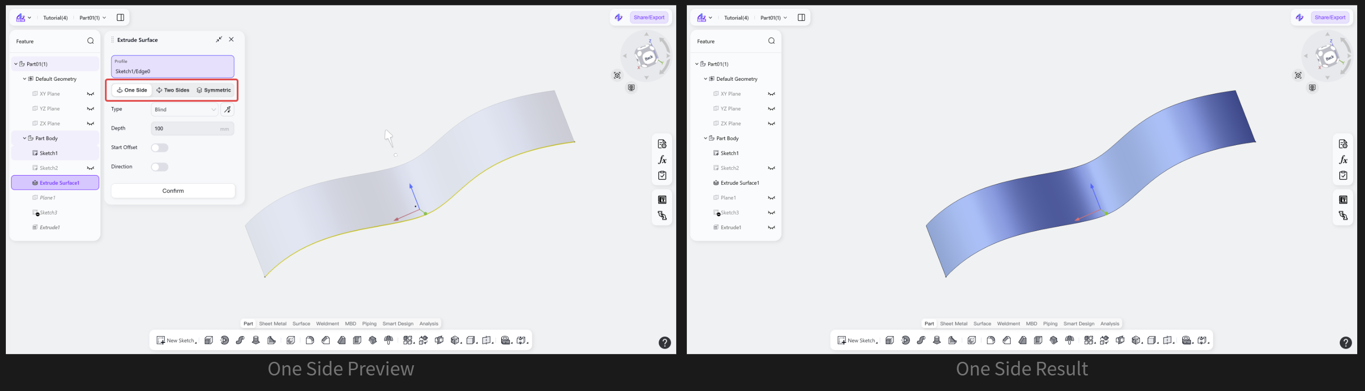
Extrusion Method: One Side
Extrudes the sketch profile, model edge, or curve in one direction to generate a surface.
Steps: Select "One Side".
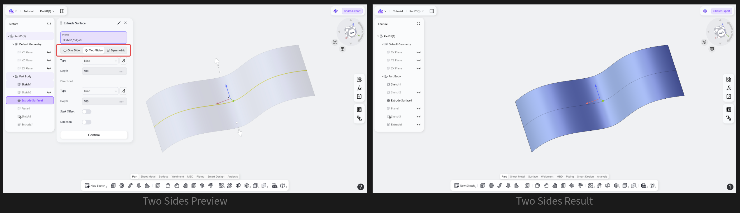
Extrusion Method: Two Sides
Extrudes the selected profile or curve in two opposite directions to generate a surface.
Steps: Select "Two Sides".
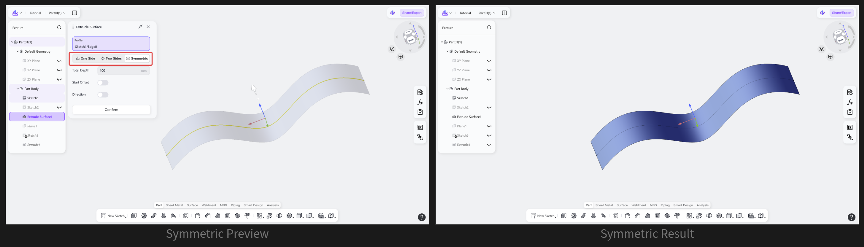
Extrusion Method: Symmetric
Extrudes the selected profile or curve by an equal distance in both directions.
Steps: Select "Symmetric".
Extrusion Type
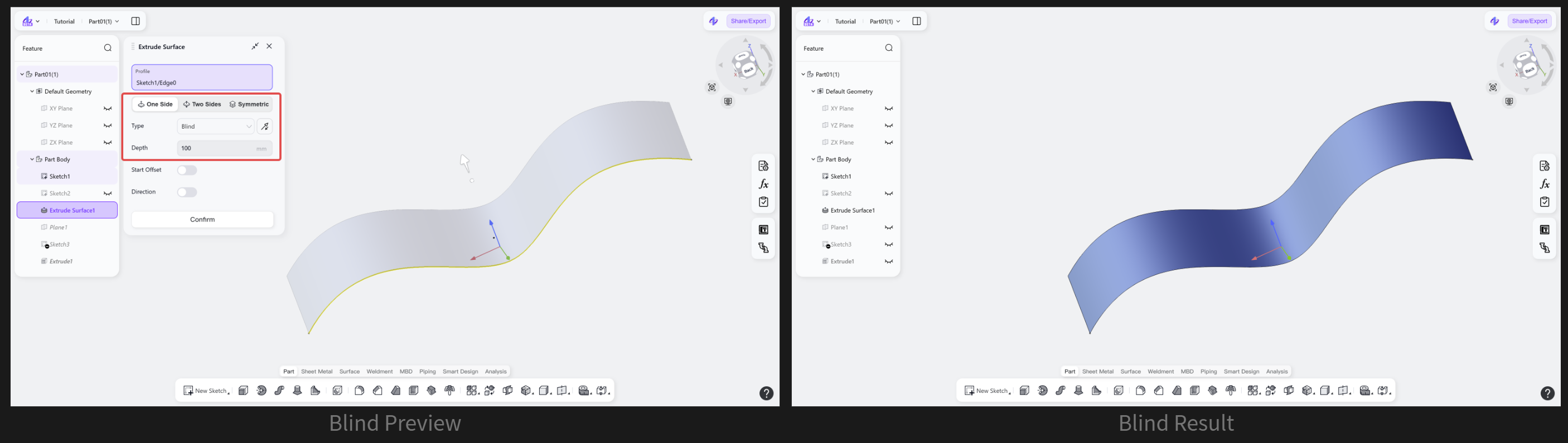
Extrusion Type: Blind
Extrudes the selected profile or curve in the specified direction by a fixed distance.
Steps
Select "Blind".
(Optional) Click "Backward" to switch the extrusion direction.
Enter the required depth.
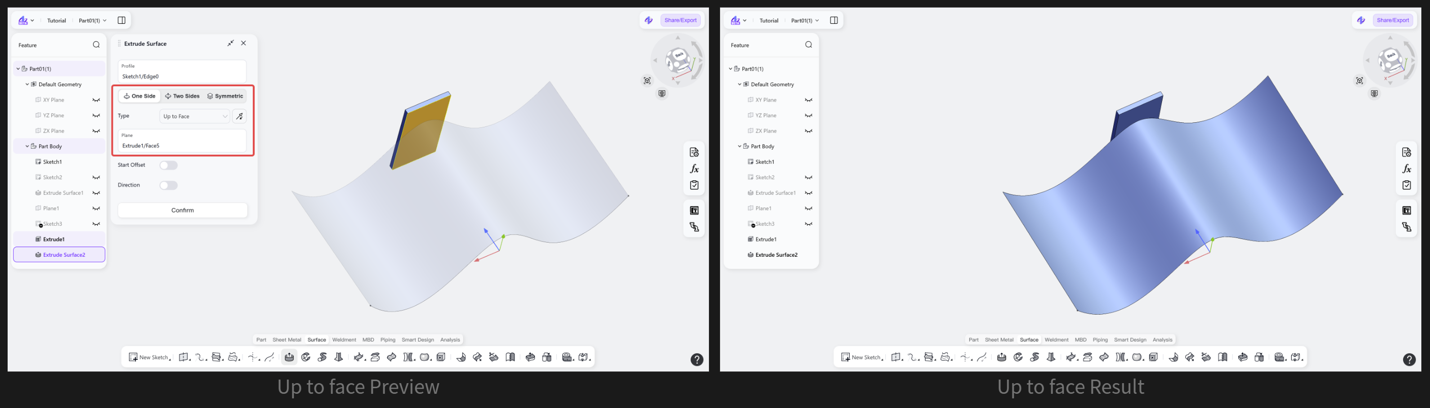
Extrusion Type: Up to face
Extrudes from the sketch profile, model edge, or curve to the selected face.
Steps
Select "Up to face".
(Optional) Click "Backward" to switch the extrusion direction.
Select an existing face as the target face to end the extrusion.
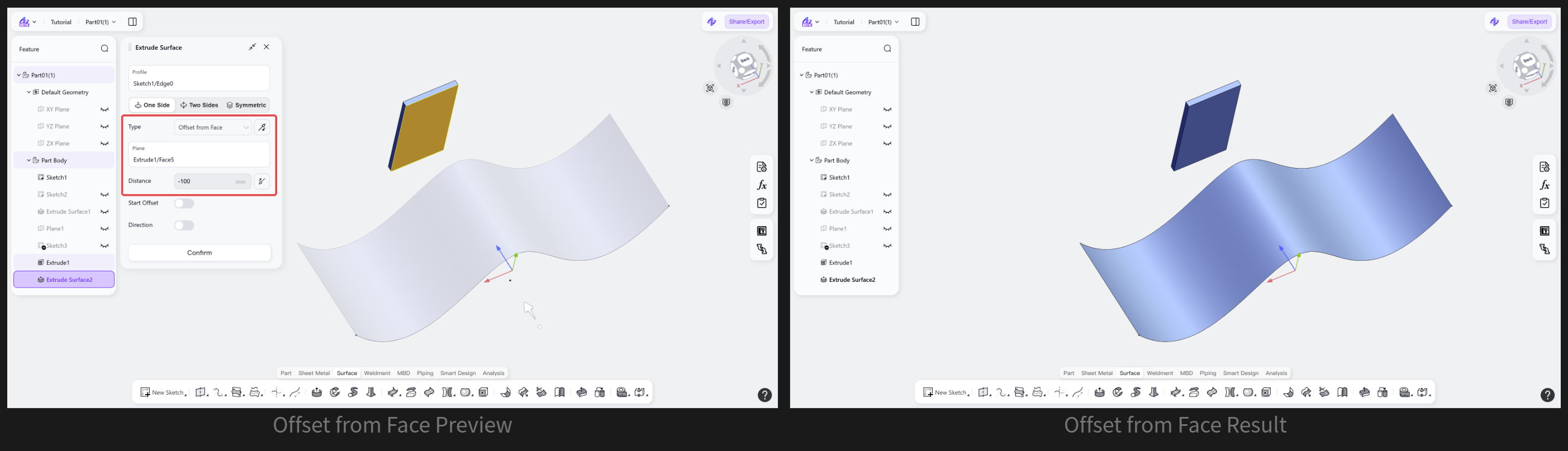
Extrusion Type: Offset from Face
Extrudes the sketch profile, model edge, or curve to a position at a specified distance from a selected face.
Steps
Select "Offset from Face".
(Optional) Click "Backward" to switch the extrusion direction.
Select the target face to extend to.
Enter the offset distance from the target face.
Start Offset
Start Offset: Equidistant
Starts the extrusion at a distance offset from the sketch profile, model edge, or curve.
Steps
Select "Equidistant".
Set the offset value.
(Optional) Click "Backward" to switch the extrusion direction.

Extrusion Direction
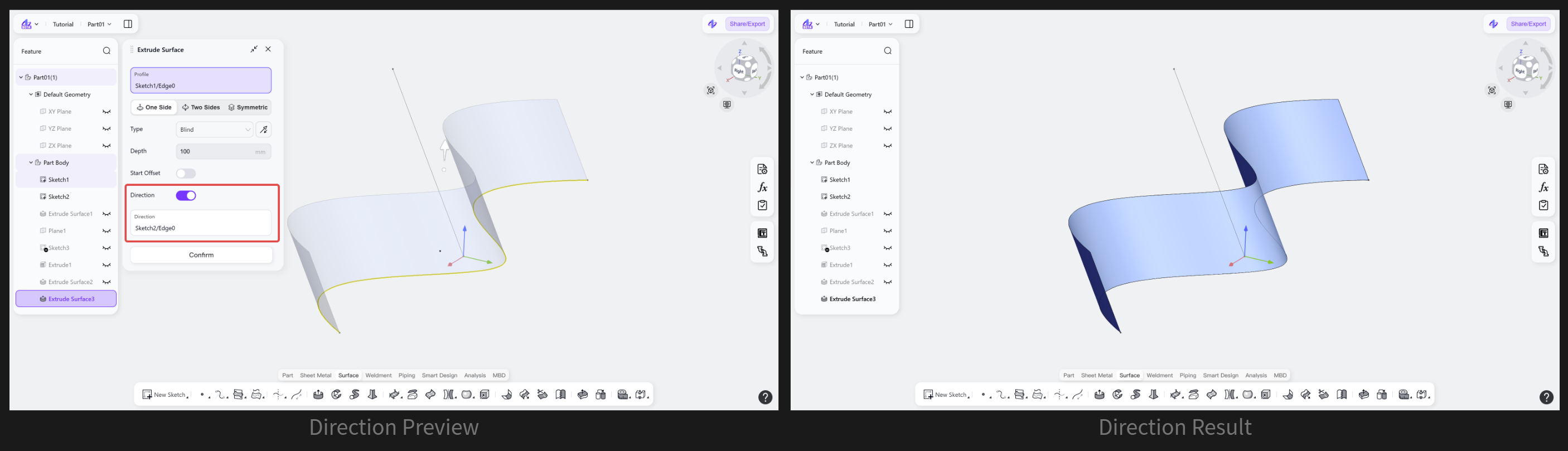
Extrusion Direction: Direction
Allows changing the extrusion orientation of the surface, using a "Line" for direction guidance.
Steps
Select "Direction".
Select a line to define the extrusion direction.
Notes
Extrusion objects support sketch profiles, model edges, and curves.
Extrusion depth supports direct value input or dynamic adjustment by dragging the arrow.