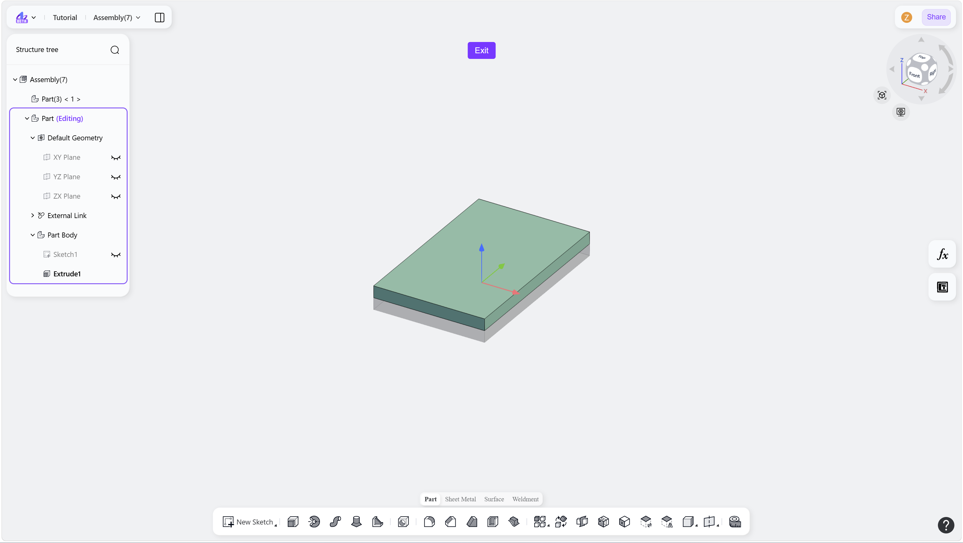
This workflow enables geometry creation within a part while referencing existing assembly components. Associative links are created automatically to maintain design intent and update consistency.
Steps
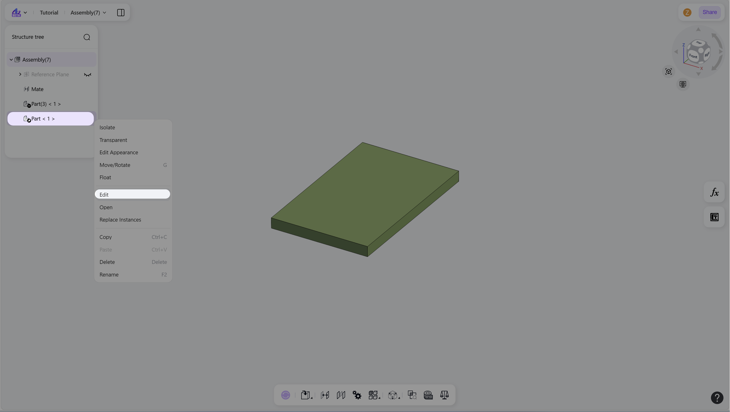
Right-click the node of a newly created part in the structure tree, then select "Edit" to enter Edit Mode.
Create geometry with in-context references:
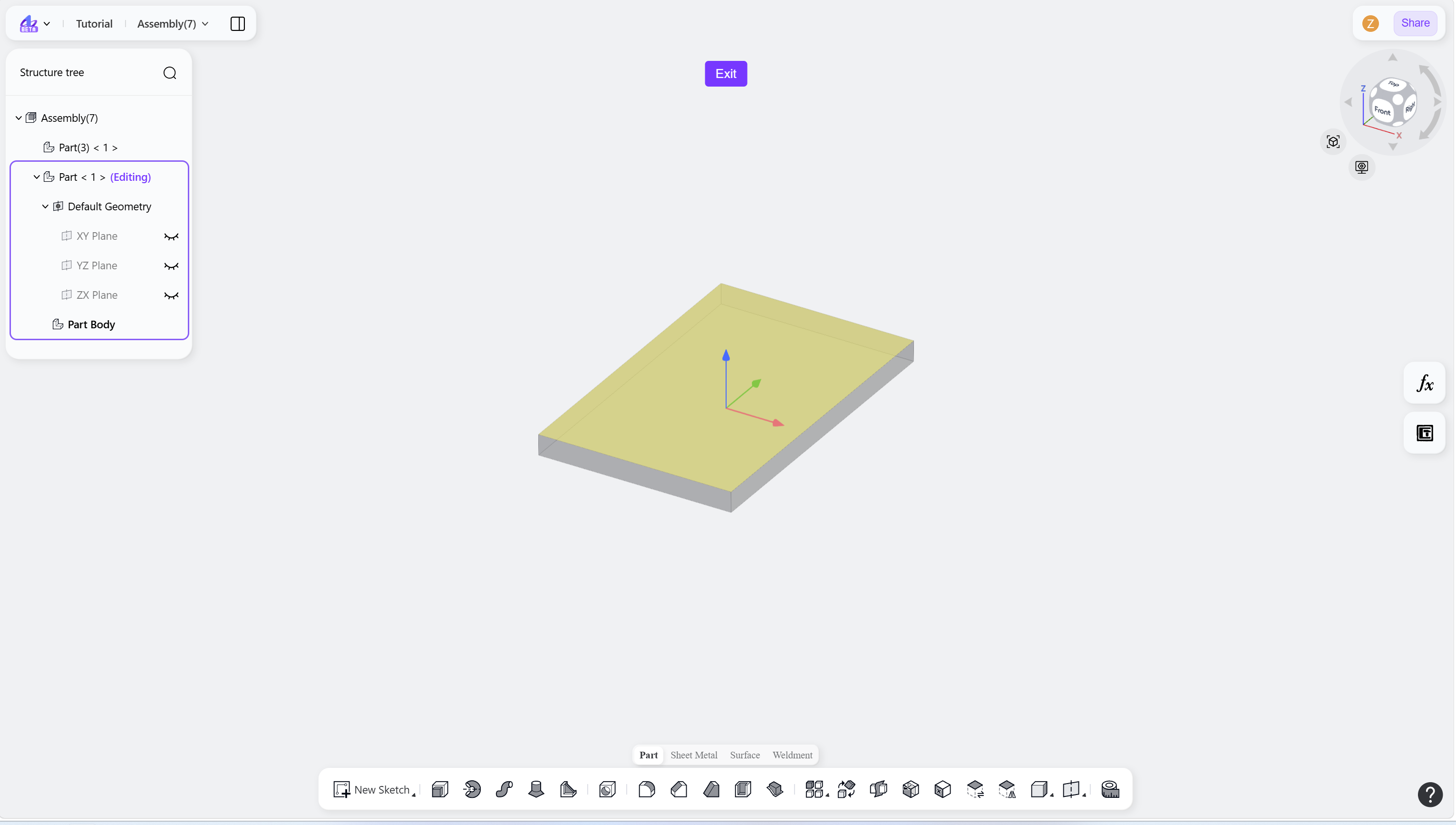
Click "New Sketch" on the toolbar. Hold Alt and select a face of another component as the sketch plane.
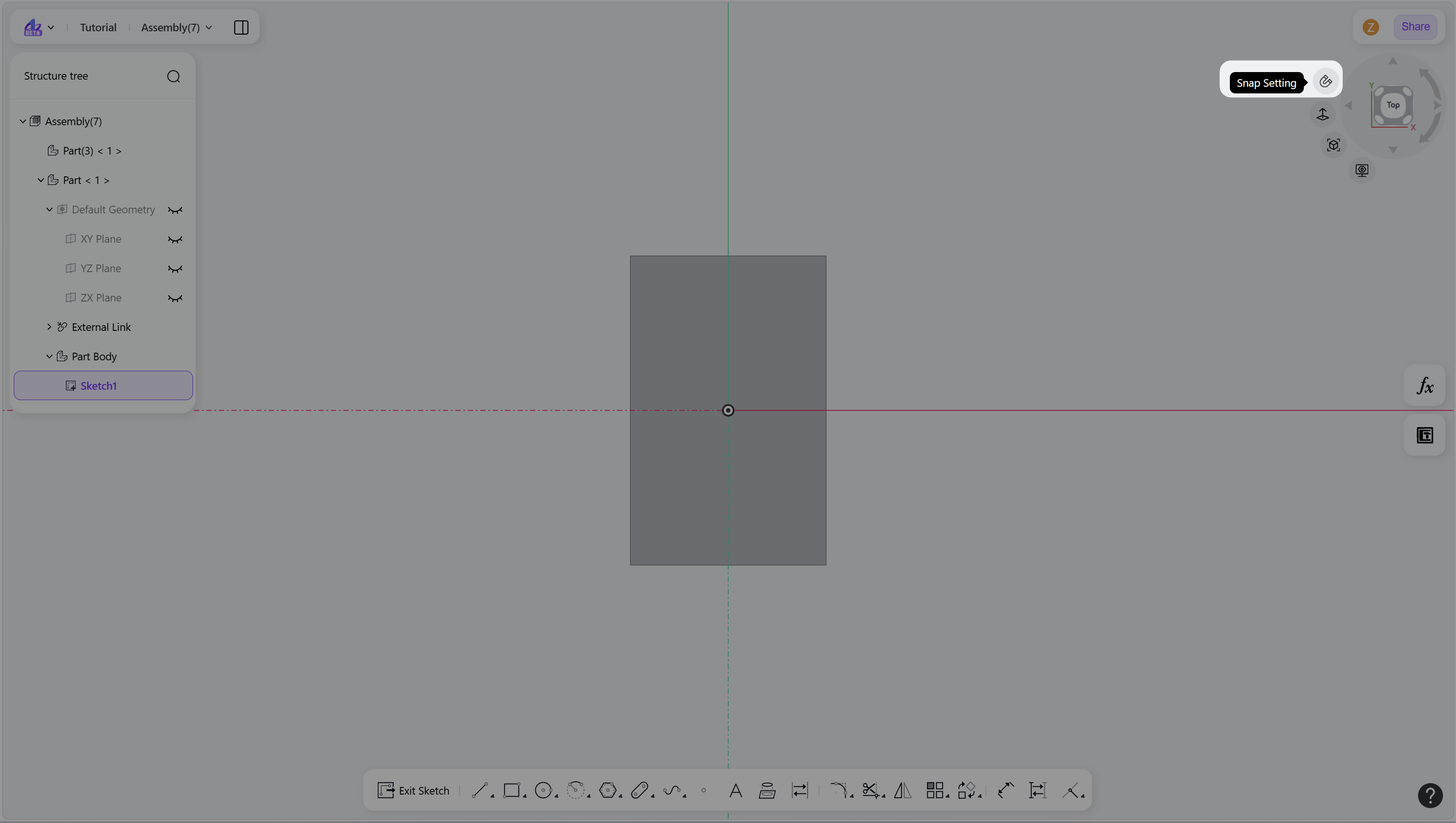
Click "Snap Setting" next to View Navigation Cube. Then create sketch geometry using existing component features as references. Associative references are created automatically.
Click "Exit Sketch" on the toolbar. Then create features based on the sketch.
Click "Exit" at the top of the interface to leave the part editing environment.
Notes
A fastened mate is automatically created between the new part and the referenced face or feature.
This fastened mate defines the initial positioning of the new part within the assembly.
Step 1 - Right-click the new part node in the structure tree, then select "Edit":
Step 2-1 - Hold Alt and select a face of another component as the sketch plane:
Step 2-2 - Enable Snap Setting and create sketches using existing geometry references:
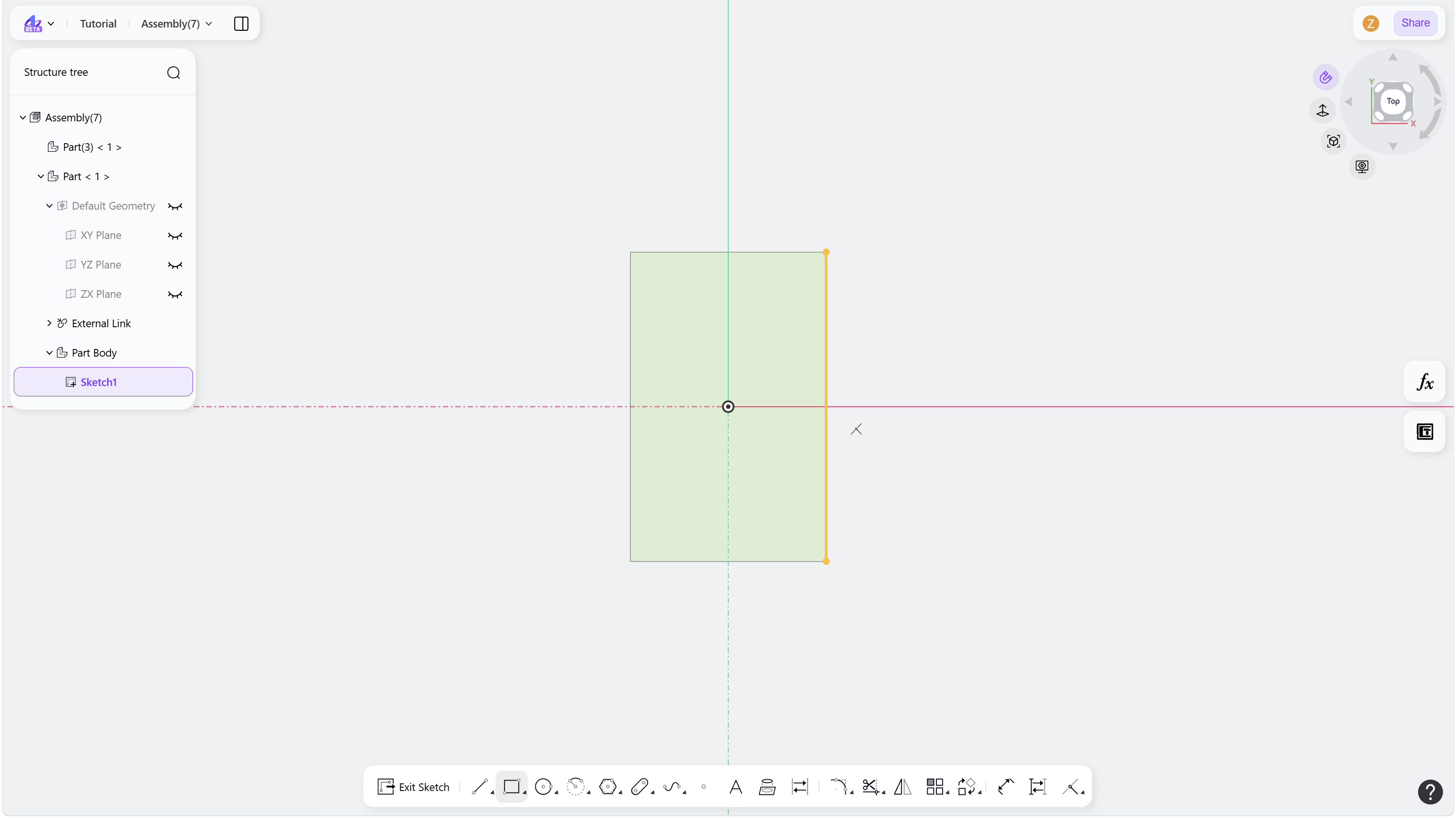
Step 2-3 - Exit Sketch mode and proceed with feature creation:
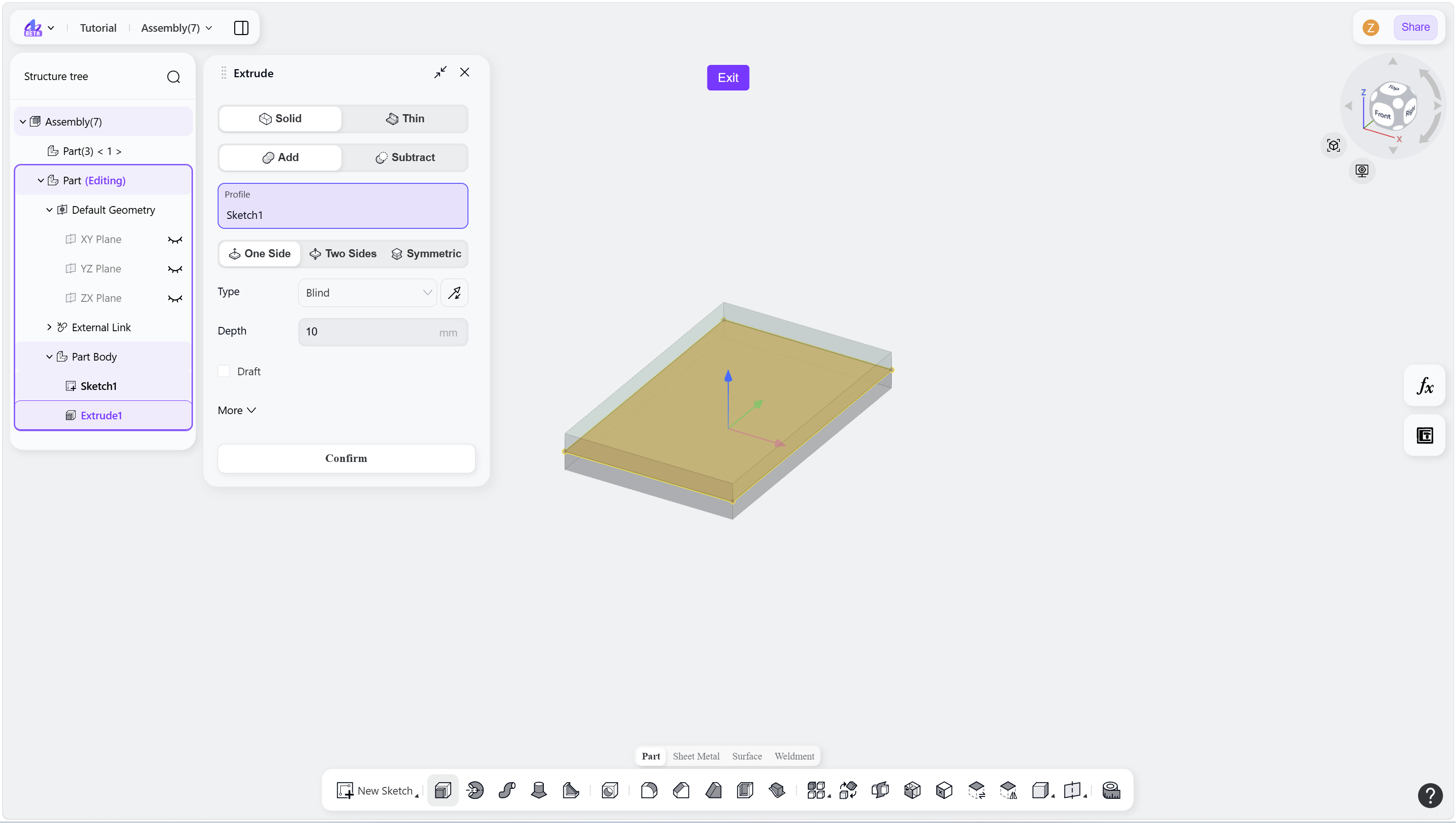
Step 2-4 - Click Exit to leave the part editing environment: