

The Control Point Spline tool creates smooth free-form curves by placing a sequence of control points. It is commonly used for non-standard profiles, organic shapes, and reference curves in surface modeling.
Steps
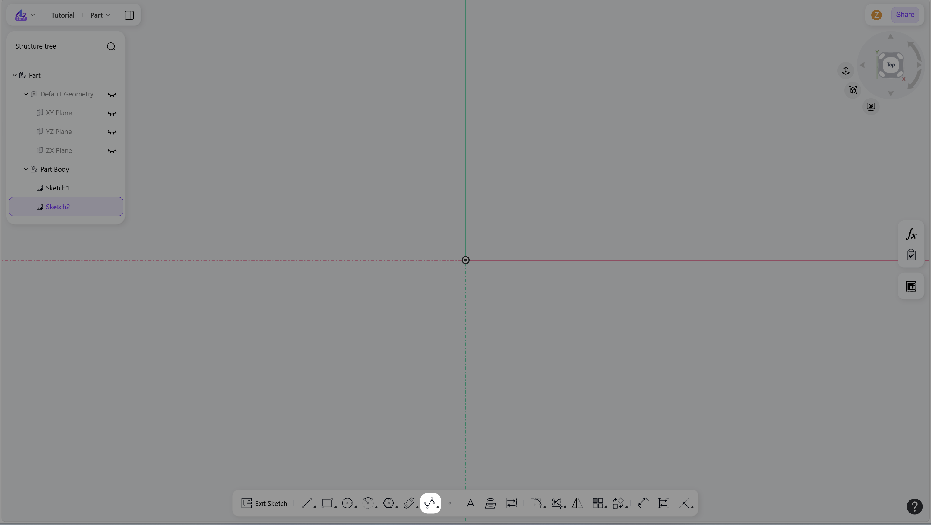
Click the “Control Point Spline” icon in the toolbar to enter Control Point Spline mode.
Create a Control Point Spline:
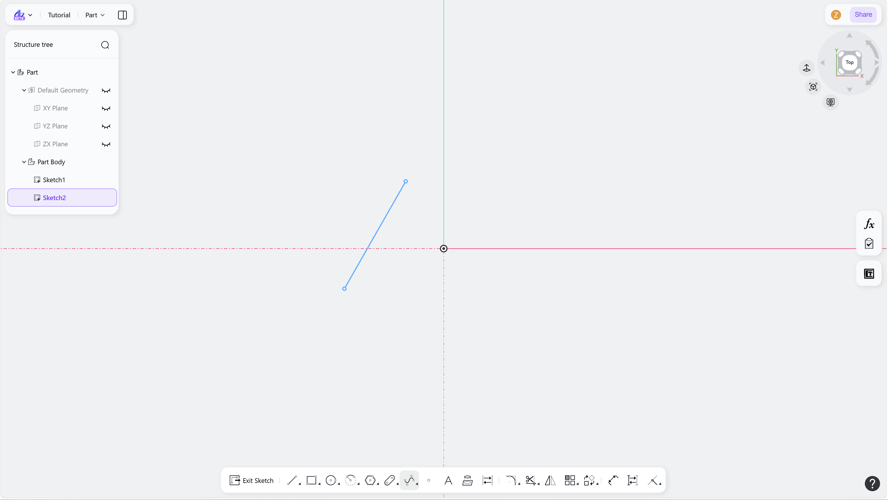
Left-click to define the first control point.
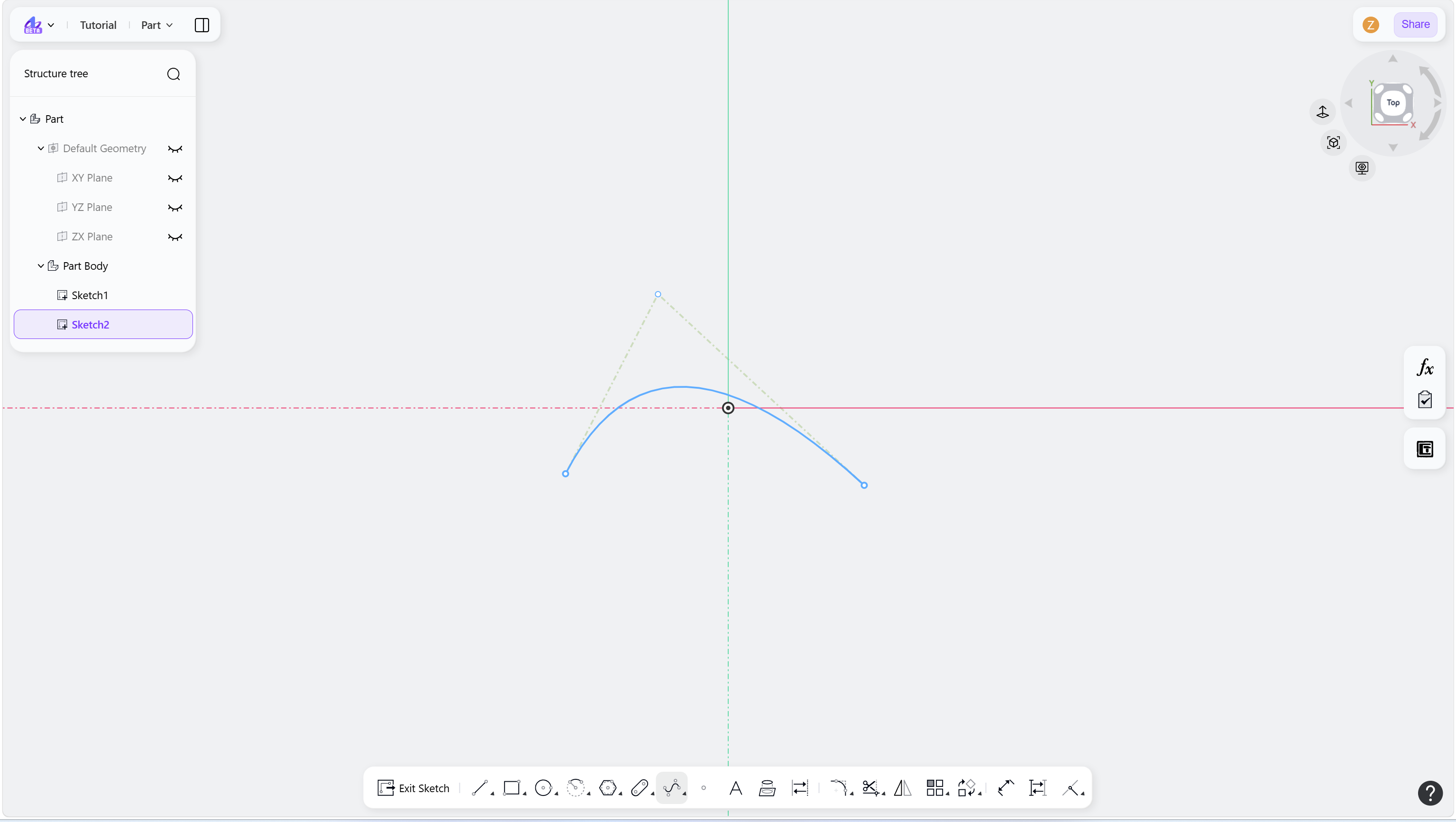
Move the cursor and left-click again to place the next control point.
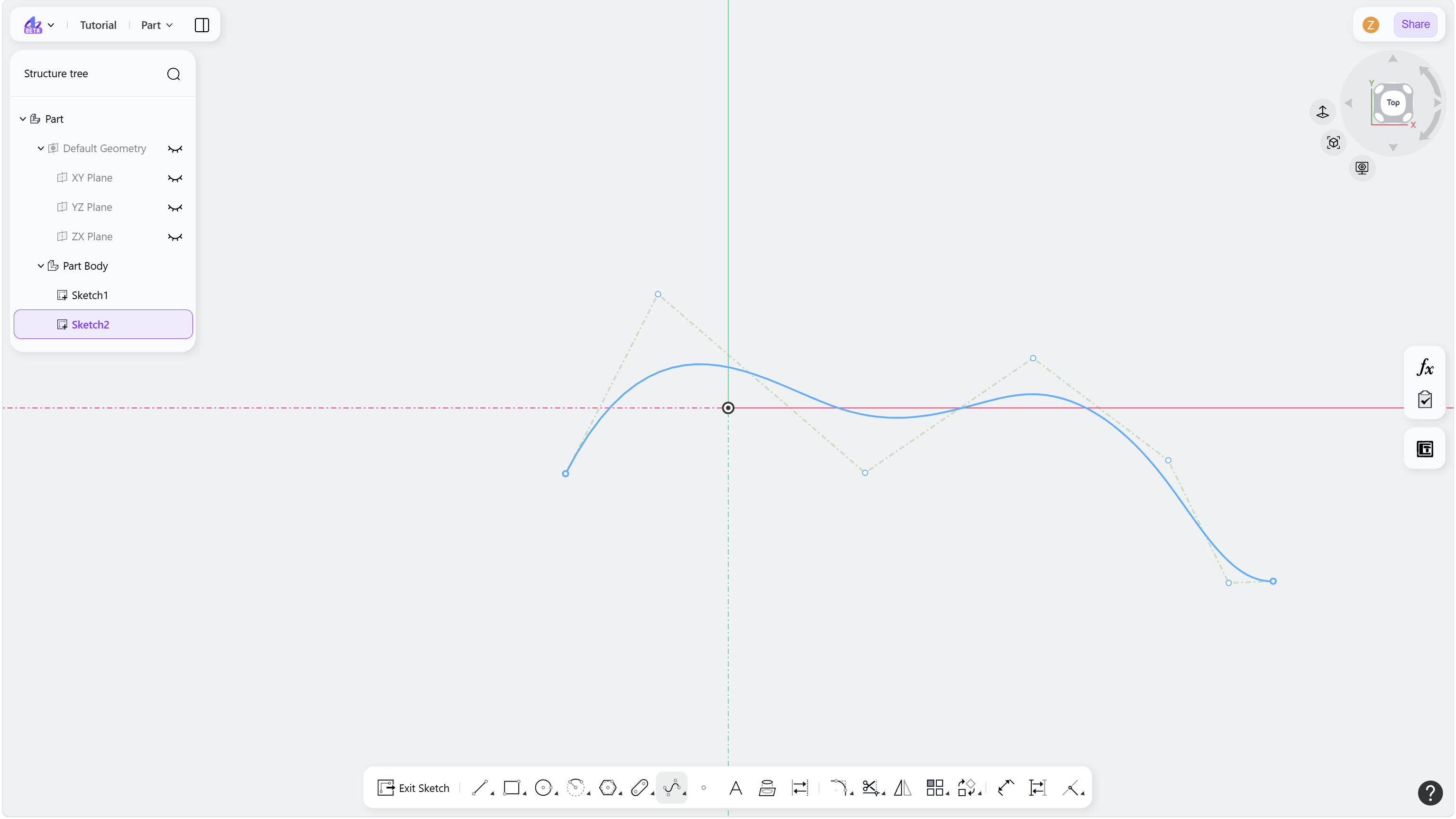
Continue clicking to add more control points. The spline updates in real time.
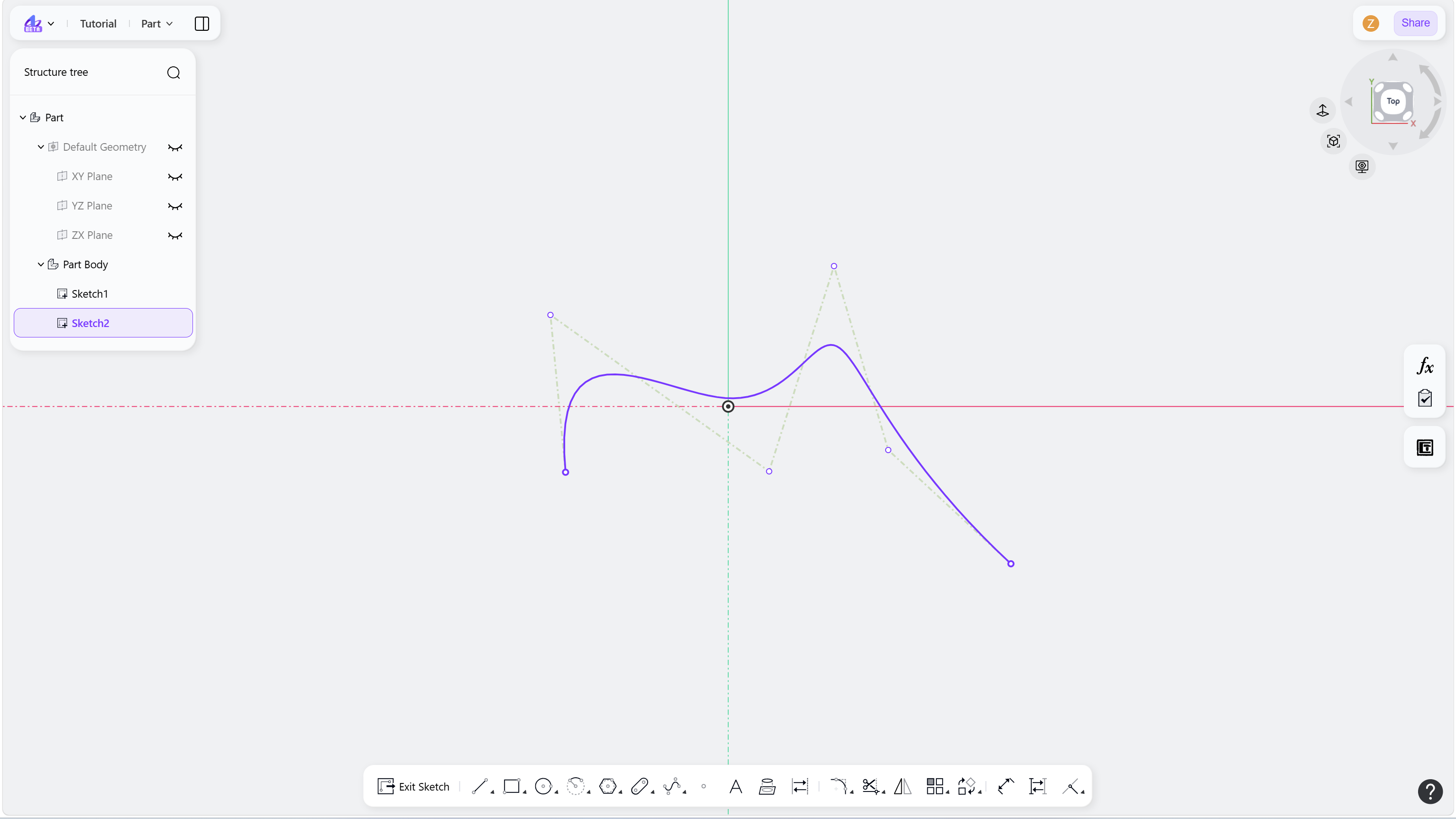
Drag control points to adjust the curve shape.
(Optional) Apply geometric constraints to control points.
Right-click or press Esc to finish the spline.
Right-click or press Esc again to exit.
Step 1 - Click the "Control Point Spline" icon in the toolbar:
Step 2 - Left-click to define the first control point:
Step 3 - Left-click again to define the next control point:
Step 4 - Continue clicking to add more control points:
Step 5 - Right-click or press Esc to finish the spline:
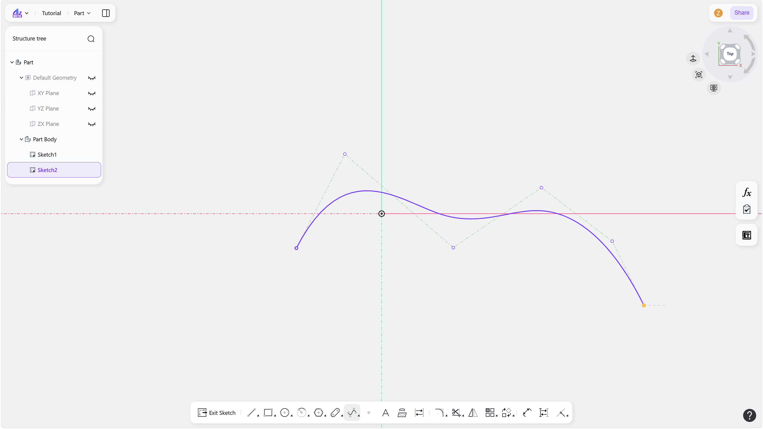
Step 6 - Drag any control points to adjust the shape of the spline:
Notes
Constraints can be applied to control points. Guide lines are displayed for visual reference only and cannot be selected or constrained.