

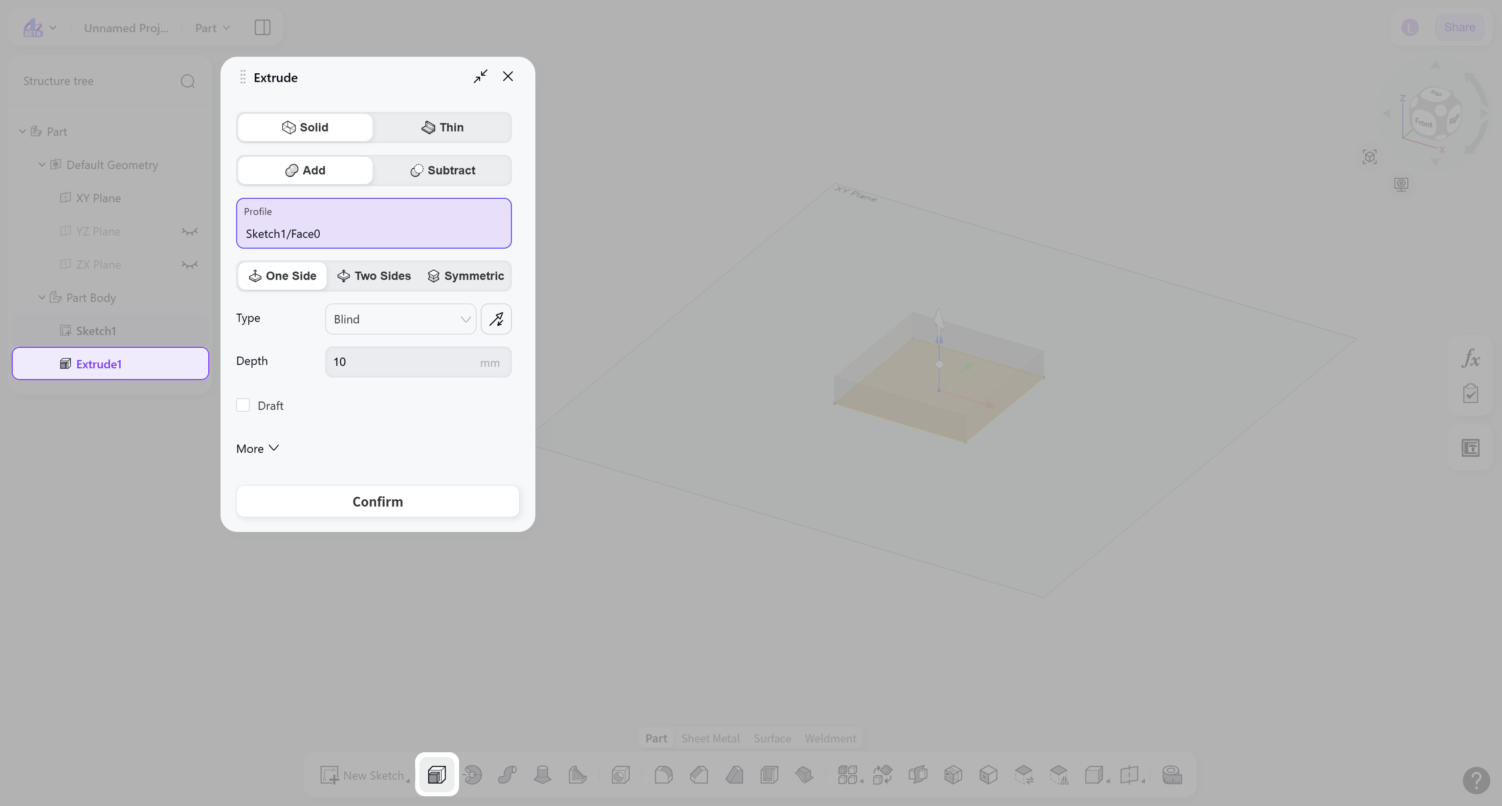
The Extrude tool converts 2D sketches into 3D solids in the Part module. By extending a sketch in a specified direction, solids can be created with thickness or depth, such as cuboids and cylinders.
Steps:
Select the feature type: "Solid" or "Thin".
Select the boolean type: "Add" or "Subtract".
Select the sketch profile to be extruded.
Select the extrusion direction mode: "One side", "Two sides", or "Symmetric".
Select the extrusion type and set the termination condition.
(Optional) Enable "Draft" to apply a draft angle to the extrusion side faces.
(Optional) Enable "Start Offset" to set the offset distance of the extrusion start position.
(Optional) Enable "Direction" to select reference geometry for the extrusion direction.
Feature Type
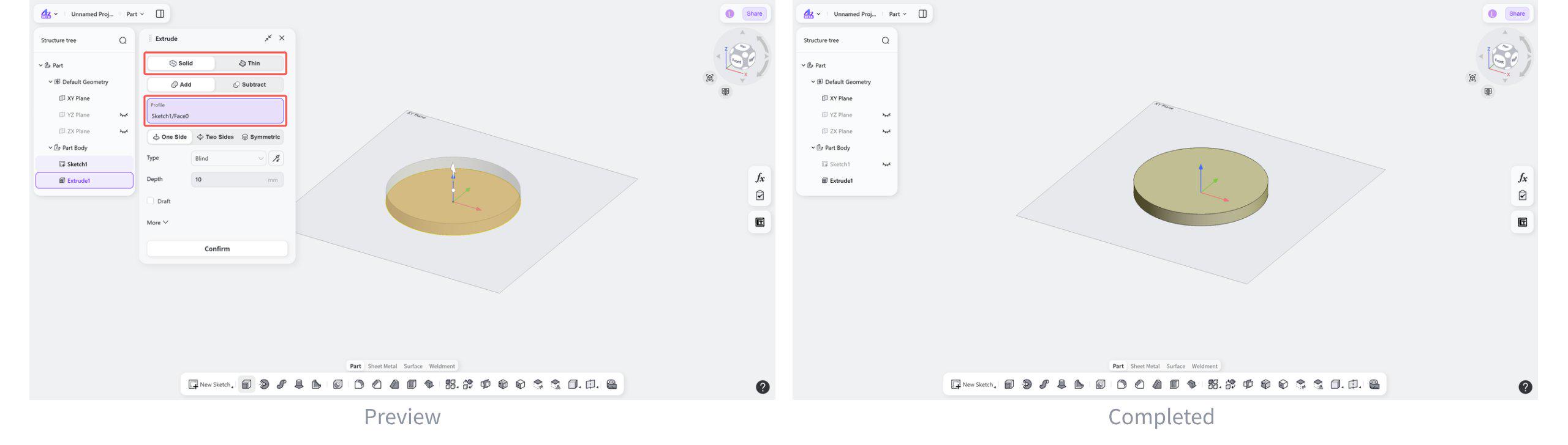
Feature Type: Solid
Extrudes a sketch along a single direction to create a solid.
Steps:
Select "Solid".
Select the closed profile to be extruded in the sketch.
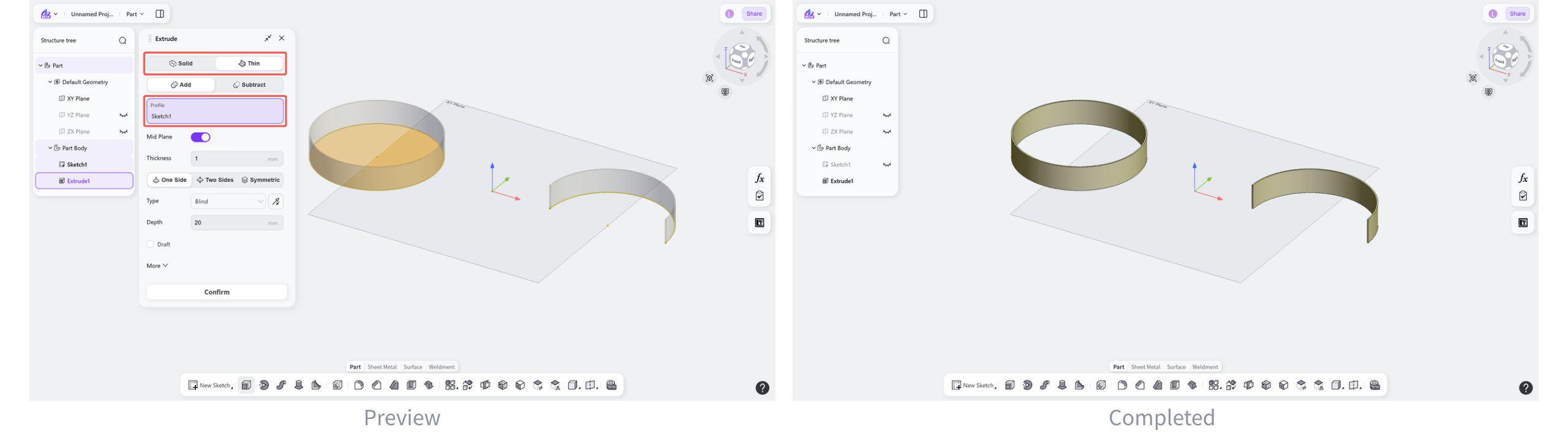
Feature Type: Thin Wall
Creates a thin-wall feature by extrusion.
Steps:
Select "Thin".
Select a closed profile or open curve in the sketch.
Set the thickness.
(Optional) Select "Symmetric Thickness" to apply the thickness equally on both sides of the sketch.
Boolean Type
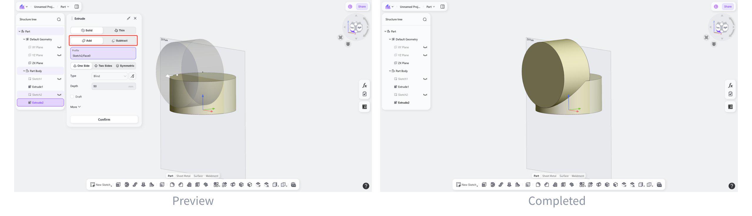
Boolean Type: Addtion
Merge the newly created extruded body with the existing solid into a single body.
Click "Add".
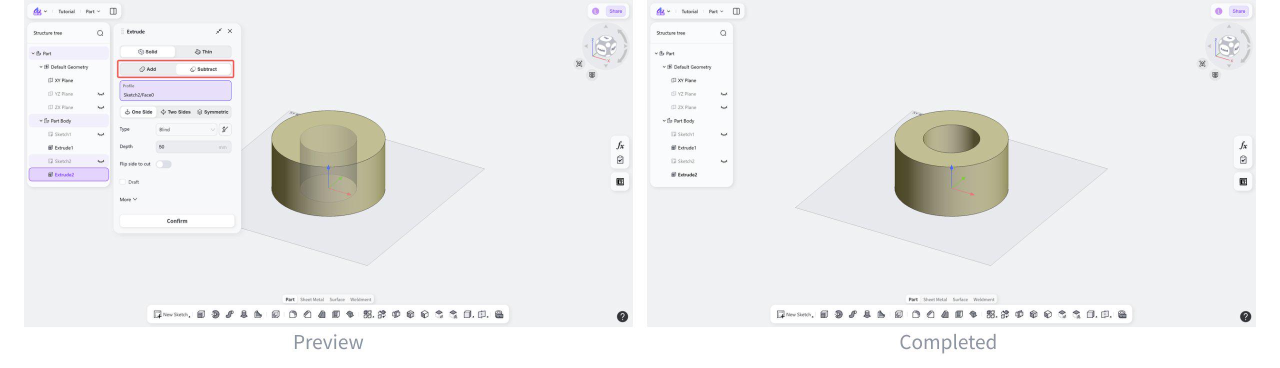
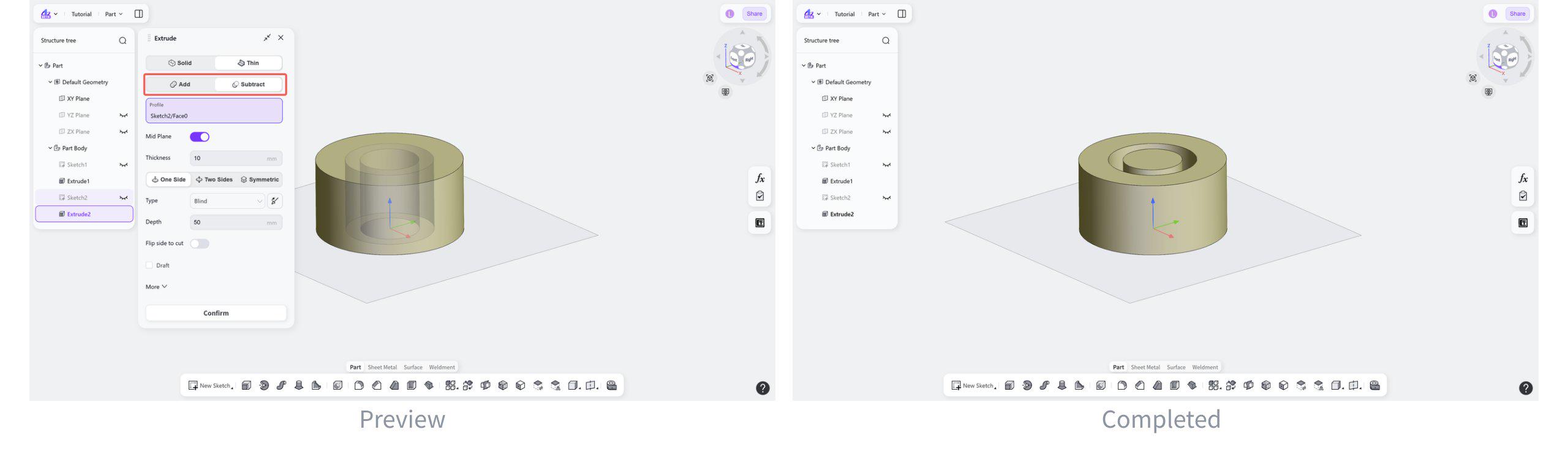
Boolean Type: Subtraction
Subtracts the newly created extrusion from the existing solid and removes the overlapping material from the original body.
Select "Subtract".
Extrusion Method
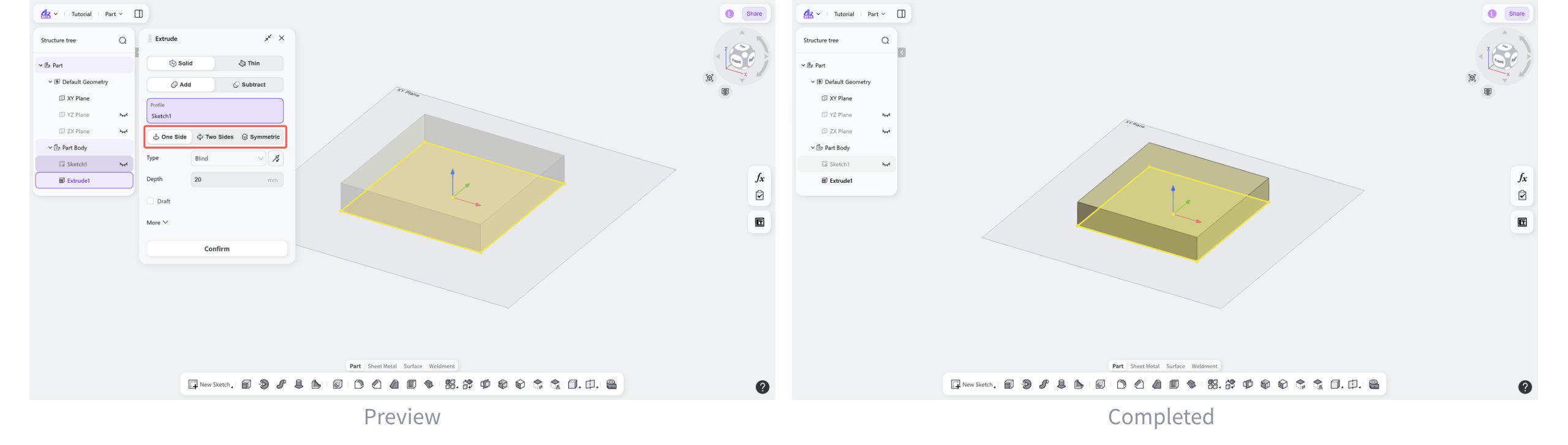
Extrusion Method: One Side
Extrudes the sketch in one direction to create a solid or thin-wall feature.
Select "One Side".
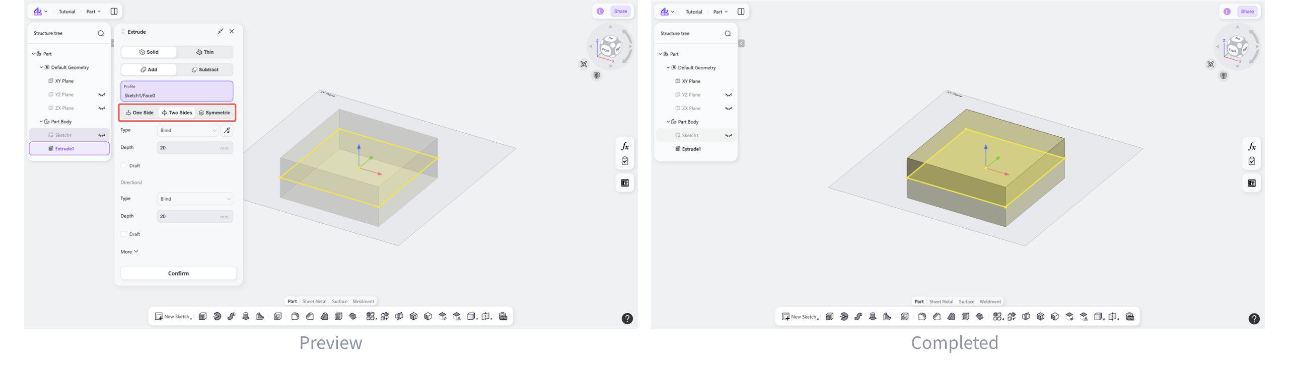
Extrusion Method: Two Sides
Extrudes a solid or thin-wall feature from the sketch plane in two opposite directions.
Select "Two Side".
Extrusion Method: Symmetric
Extrudes a solid or thin-wall feature symmetrically about the sketch plane.
Select "Symmetric".
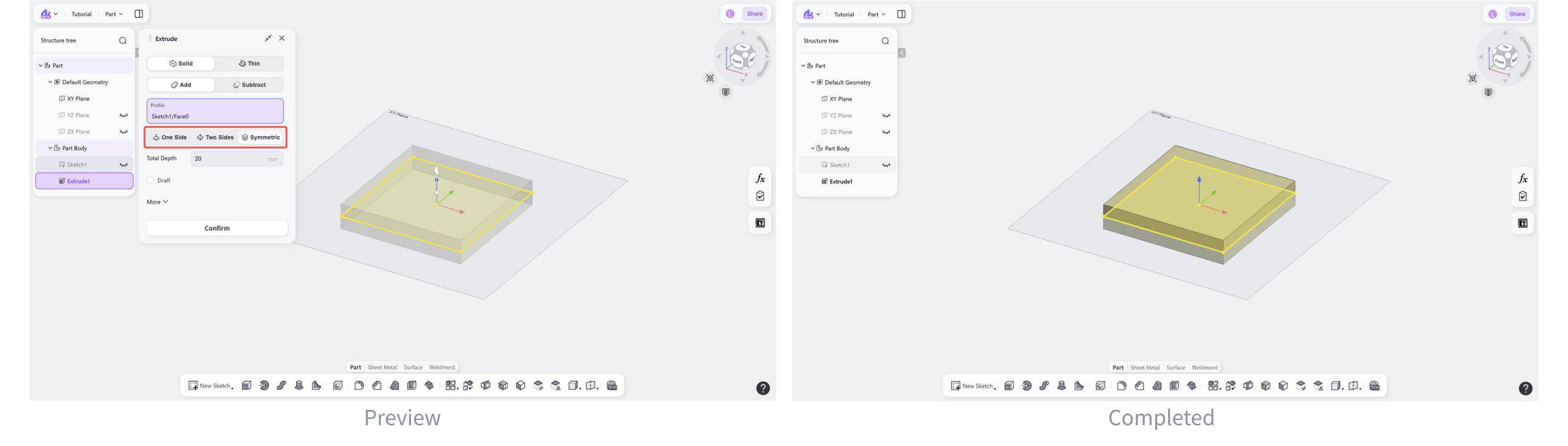
Extrusion Type
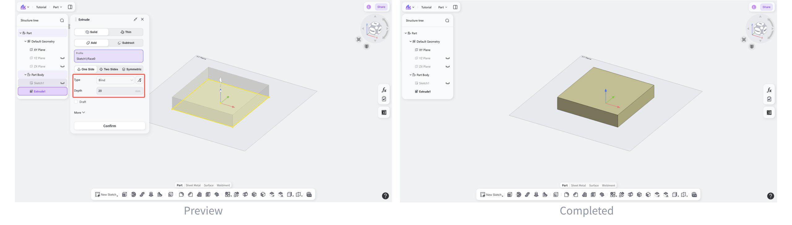
Extrusion Type: Blind
Extrudes the feature from the sketch plane by a specified distance.
Steps:
Select "Blind".
(Optional) Click the "Reverse" button to switch the extrusion direction.
Enter the required extrusion depth.
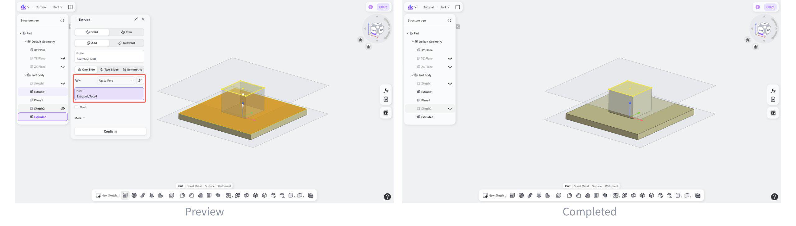
Extrusion Type: Up to Surface
Extrudes the sketch from the sketch plane to a selected surface.
Steps:
Select "Up to Surface".
(Optional) Click the "Reverse" button to switch the extrusion direction.
Select an existing face as the target face where the extrusion will end.
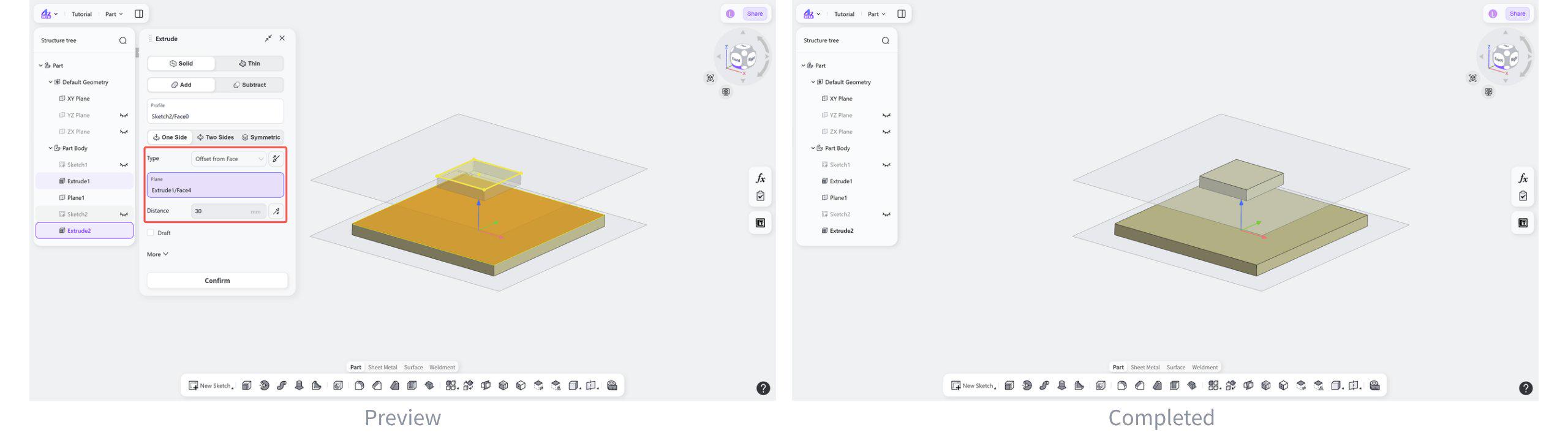
Extrusion Type: Offest from Surface
Extrudes the sketch toward a selected face while maintaining a specified offset distance from that face.
Steps:
Select "Offest from Surface".
(Optional) Click the "Reverse" button to switch the extrusion direction.
Select the target face for the extrusion.
Enter the offset distance from the selected face.
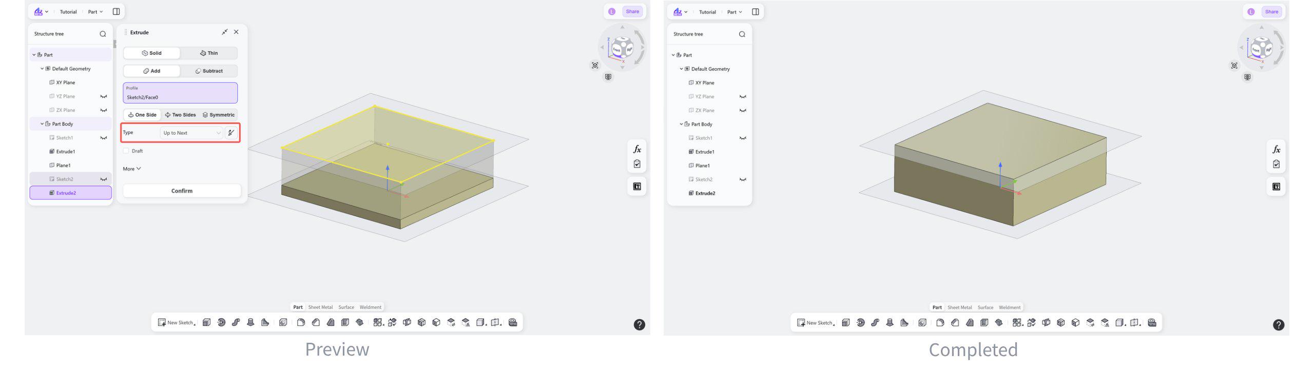
Extrusion Type: Up to Next
Extrudes the feature from the sketch plane to the next intersecting surface.
Steps:
Select "Up to Next".
(Optional) Click the "Reverse" button to switch the extrusion direction.
Extrusion Type: Through All
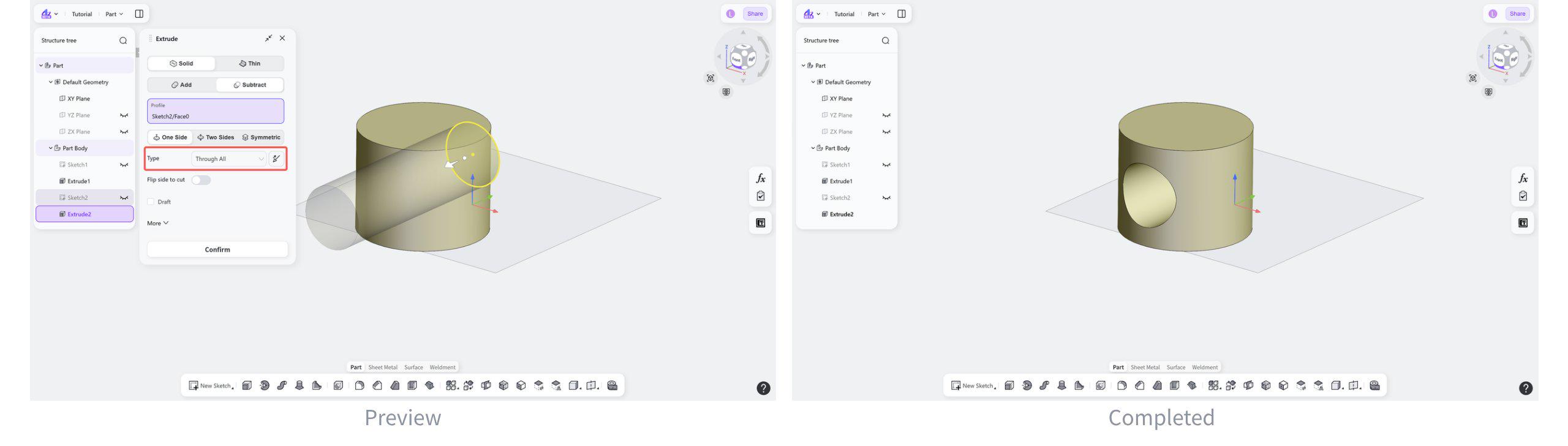
Extrudes the sketch through the entire model in the specified direction.
Steps:
Select "Through All".
(Optional) Click the "Reverse" button to switch the extrusion direction.
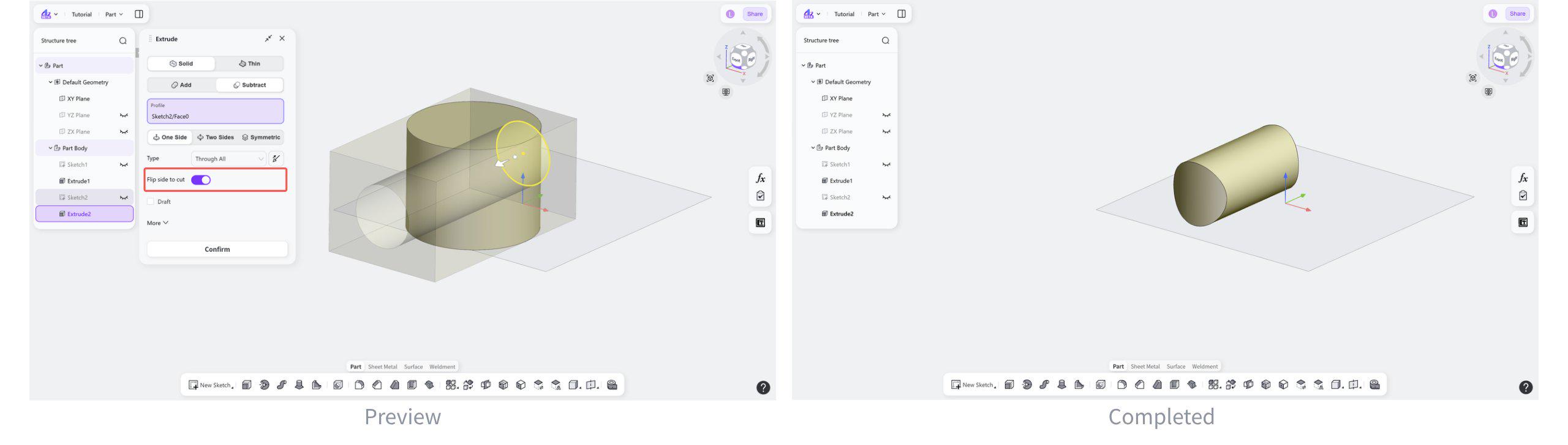
(Optional) Click the "Flip Side to Cut" button to perform a through cut in the opposite direction.
Through All
Filp side to cut
Start Offset
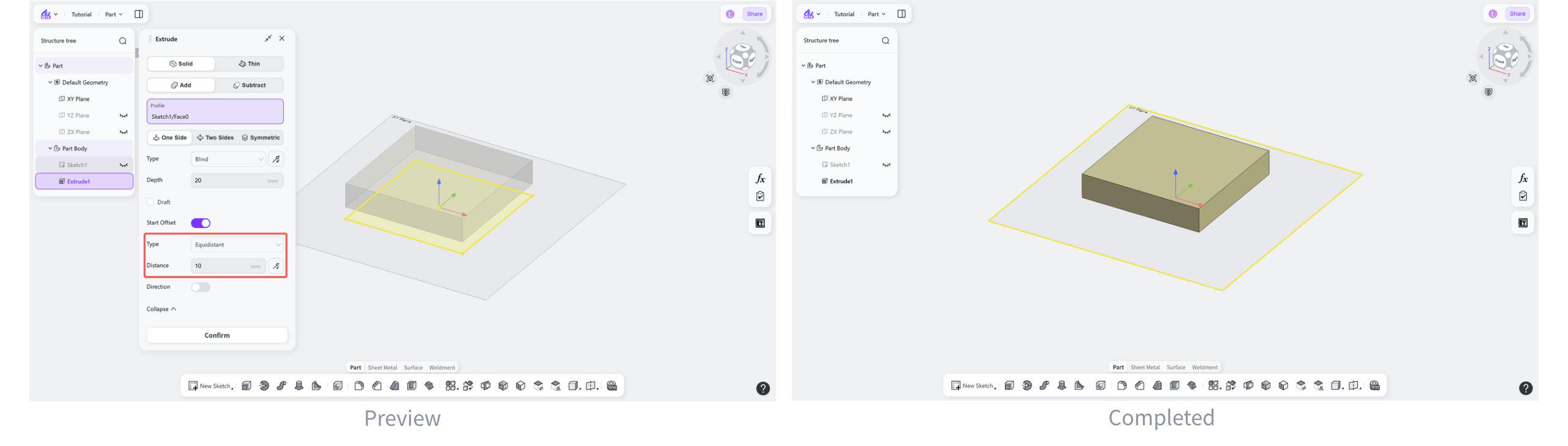
Start Offset: Equidistant
Starts the extrusion from a plane offset from the sketch plane by a specified distance.
Steps:
Select "Equidistant".
Set the offset value.
(Optional) Click the "Reverse" button to switch the extrusion direction.
Start Offset: Object
Use a selected object as the starting position for the extrusion.
Steps:
Select "Object".
Select a point or face parallel to the sketch profile to define the offset.
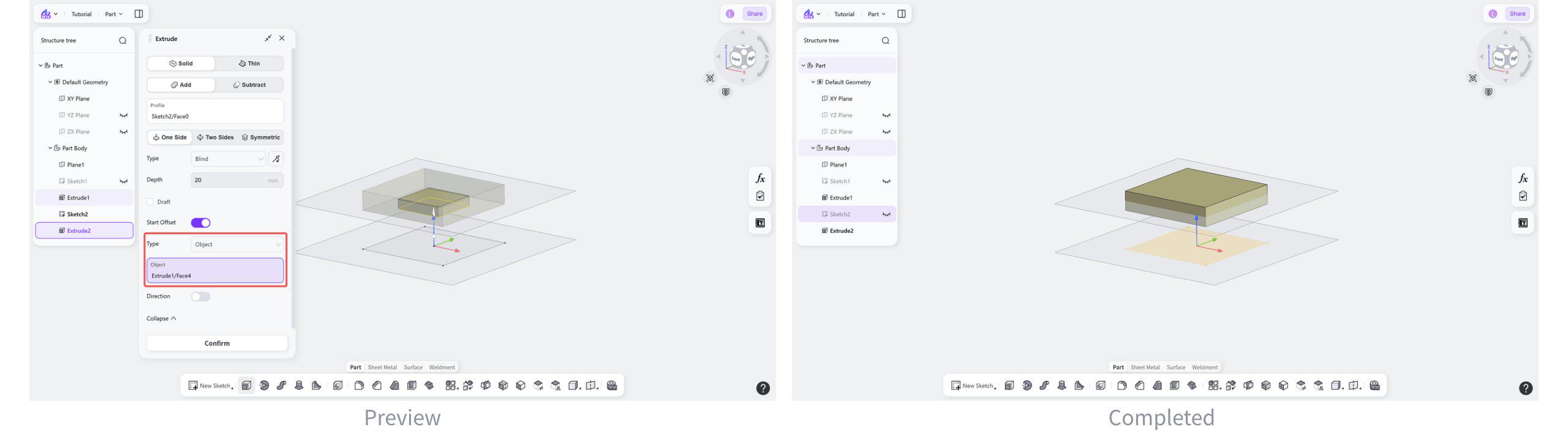
Notes:
The following objects can be selected:
Surface/Datum Plane: The extrusion starts from the selected face or datum plane.
Vertex: The extrusion starts from a plane parallel to the sketch plane and passing through the selected vertex.
Draft
Draft applies a draft angle to the side faces of a solid during an extrusion operation.
Steps:
Enable "Draft".
Set the draft angle.
(Optional) Click the "Reverse" button to switch the draft direction.
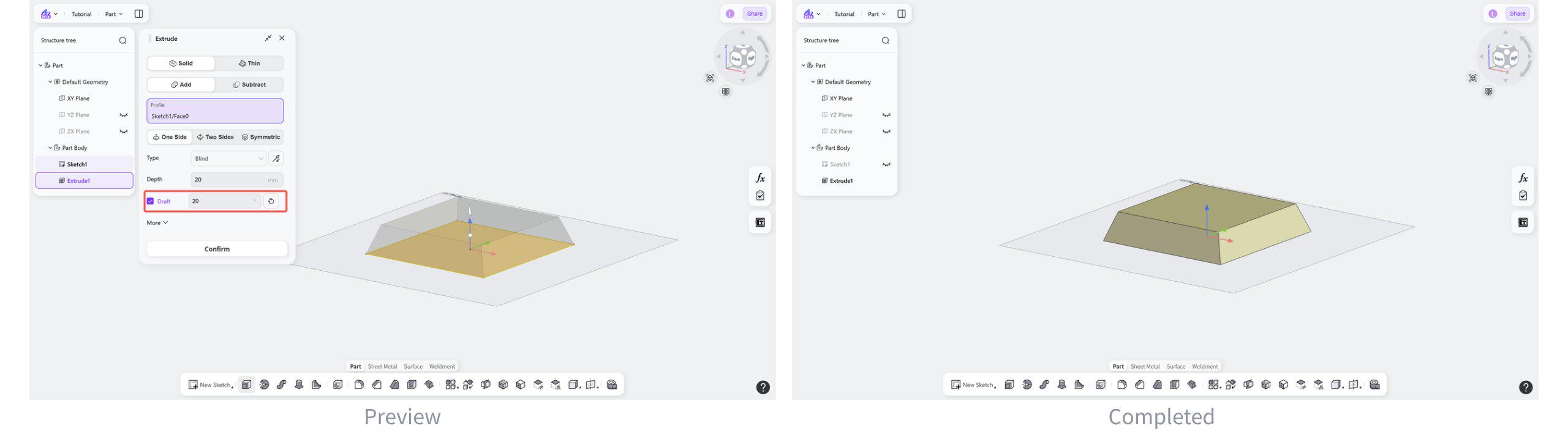
Extrusion Direction
Customize the extrusion direction during the extrusion operation.
Steps:
Enable "Direction".
Select an edge or a plane as the extrusion direction.
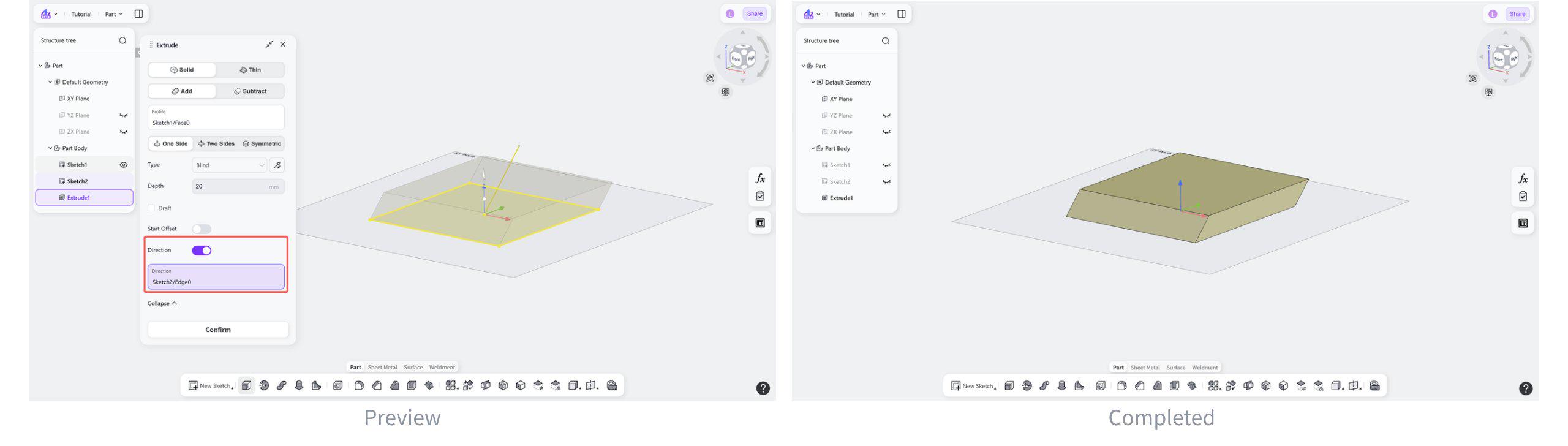
Notes:
Enable "Extrusion Direction" first and then select a reference object to define the extrusion direction:
Select a line to extrude along the line direction. The line direction cannot be perpendicular to the face normal.
Select a face to extrude along the face normal. The selected face cannot be perpendicular to the sketch or face object being extruded.