

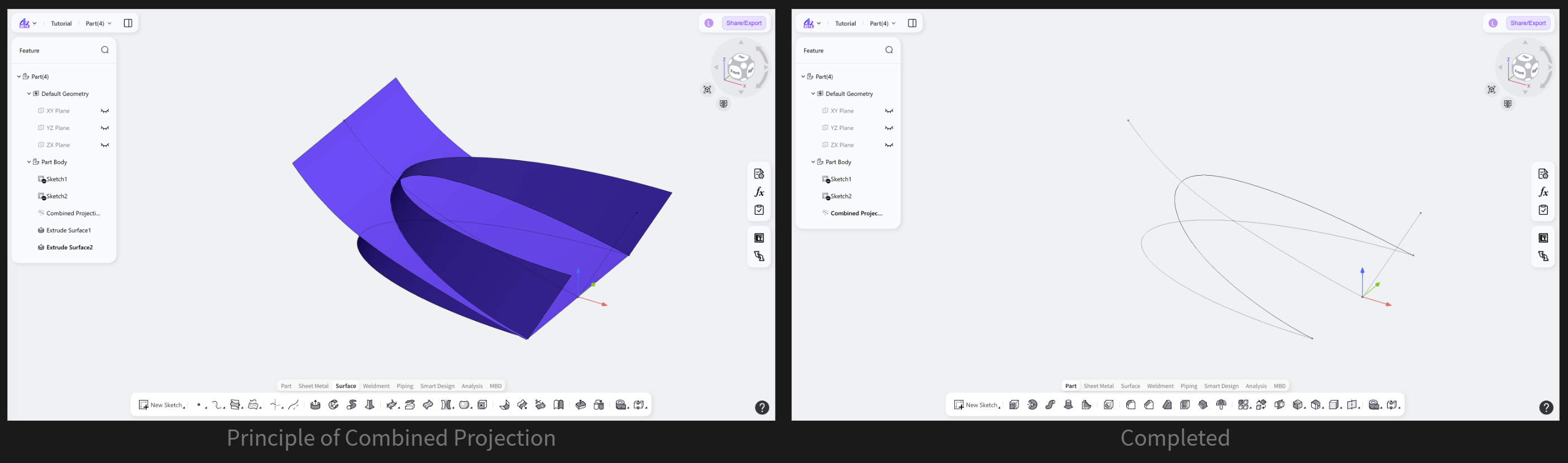
The Combined Projection tool is used to create a 3D curve from the projections of two sets of curves in surface modeling. By selecting two sets of curves and specifying a projection method for each set, either along the normal of the plane containing the curves or along a specified direction, a corresponding 3D combined projection curve can be generated.
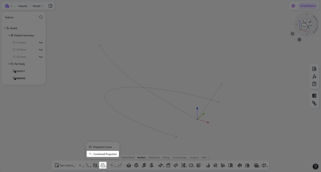
Steps:
Click the "Combined Projection" icon on the toolbar.
Select "Curve 1" and "Curve 2".
(Optional) Set the "Method 1" and "Method 2" independently to "Normal" or "Along Direction".
Click "Confirm" to create the combined curve.
Projection Method
Projection Method: Normal
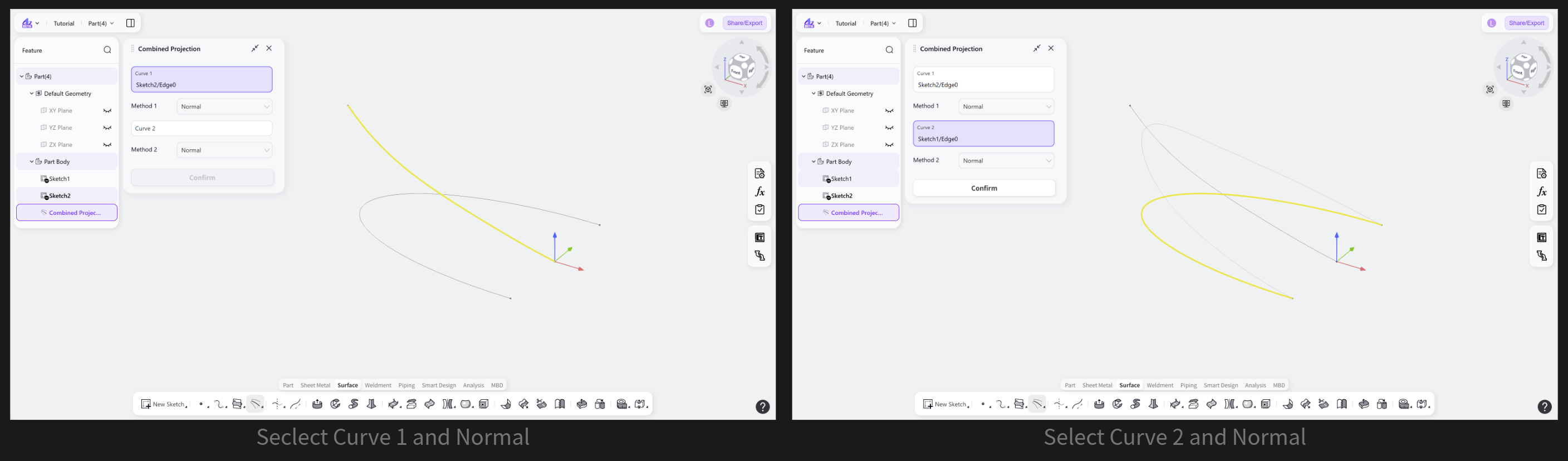
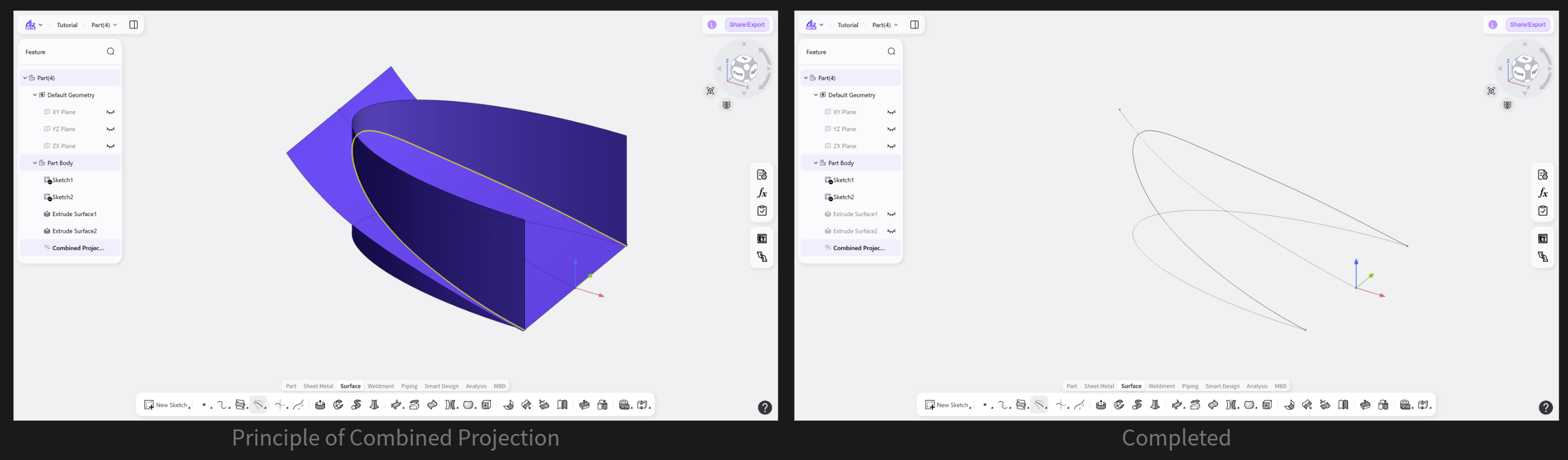
The selected curves are extruded along the normal of their sketch planes. The intersection of the extruded surfaces generated by the two sets of curves forms the combined projection curve.
Step: Select "Normal" as the direction mode.
Projection Method: Along Direction
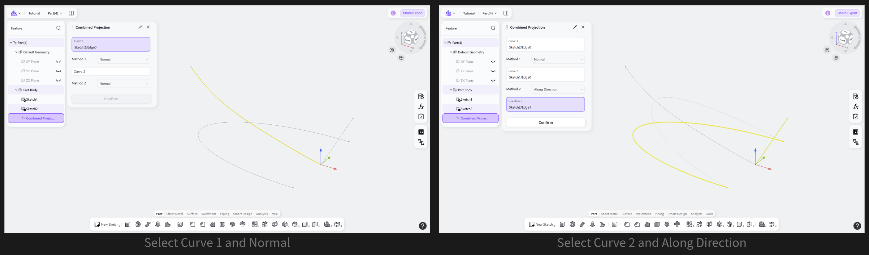
The selected curves are extruded along the selected reference direction. The intersection of the extruded surfaces generated by the two sets of curves forms the combined projection curve.
Steps:
Select "Along Direction" as the direction mode.
Click "Direction", then select a linear reference, such as a model edge, sketch line, or axis.
Notes:
For "Curve 1" or "Curve 2", one or more curves can be selected. The selected curves must lie on the same plane or on planes with the same normal direction.